Biomedical Engineering Reference
In-Depth Information
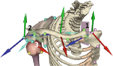
Fig. 9.5
Approximation of
supplementary joint informa-
tion using multiple regression
equations. Joint plane location
(semi-transparent magenta
planes) and perpendicular
vectors (
in cyan
) displayed
for sternoclavicular joint (
1
),
acromioclavicular joint (
2
)
and glenohumeral joint (
3
)
Data Pre-processing
This section describes how the collected data have been pre-processed in order to
generate results required for the development of the ShRm estimation algorithm and
related validation.
Joint Center Coordinates and Dimensions
Supplementary morphological information had to be extracted from the bone models
in order to fully comply with the recommendations of the International Society
of Biomechanics [
1
] which request the spatial coordinates of joint centres, such
as the scapulohumeral joint center) for the creation of specific anatomical frames.
Therefore, joint centres required for further joint motion representationwas estimated
using regression equations [
74
] applied on the described ALs.
After joint estimation the following information were available (Fig.
9.5
):
Sterno-Clavicular Joint:
•
Joint center spatial location.
•
Joint main plane and normal orientation to this plane.
Acromio-Clavicular Joint:
•
Joint center spatial location.
•
Joint main plane and normal orientation to this plane.
Gleno-Humeral Joint:
•
Joint center spatial location (HCH: RHCH for right, LHCH for left).
•
Head humerus (modeled as a sphere).