Biomedical Engineering Reference
In-Depth Information
of the skin-electrode interface. This preparation often involves shaving, scrubbing the skin,
and applying an electrolyte paste: actions unacceptable as part of routine pre
ight proce-
dures. In addition, the electrical interface characteristics deteriorate during long-term use of
these electrodes as a result of skin reactions and electrolyte drying. Dry or
pasteless elec-
trodes
can be used to get around the constraints of electrolyte-interface electrodes. Pasteless
electrodes incorporate a bare or dielectric-coated metal plate, in direct contact with the skin,
to form a very high impedance interface. By using an integral high-input-impedance
ampli
fl
er, it is possible to record a signal through the capacitive or resistive interface.
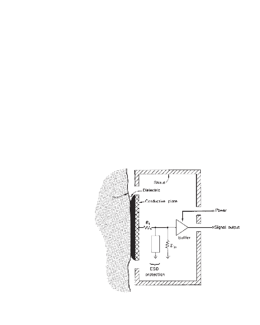
Figure 1.10 presents the constitutive elements of a capacitive pasteless bioelectrode. In
it, a highly dielectric material is used to form a capacitive interface between the skin and
a conductive plate electrode. Ideally, this dielectric layer has in
fi
fi
nite leakage resistance, but
in reality this resistance is
fi
finite and decreases as the dielectric deteriorates. Signals
presented to the bu
er stage result from capacitive coupling of biopotentials to the network
formed by series resistor R1 and the input impedance
Z
in
of the bu
ff
ff
er ampli
fi
er. In addi-
tion, circuitry that is often used to protect the bu
er stage from ESD further attenuates
available signals. Shielding is usually provided in the enclosure of a bioelectrode assem-
bly to protect it from interfering noise. The signal at the output of the bu
ff
er has
low impedance and can be relayed to remotely placed processing apparatus without atten-
uation. External power must be supplied for operation of the active bu
ff
er ampli
fi
er circuitry.
A dielectric substance is used in capacitive biopotential electrodes to form a capacitor
between the skin and the recording surface. Thin layers of aluminum anodization, pyre
varnish, silicon dioxide, and other dielectrics have been used in these electrodes. For
example, 17.5-
ff
film is easily prepared by anodic treatment, resulting in elec-
trode plates that have a dc resistance greater than 1 G
µ
m (0.7-mil)
fi
Ω
and a capacitance of 5000 pF at
Figure 1.10
Block diagram of a typical capacitive active bioelectrode. A highly dielectric material
is used to form a capacitive interface between the skin and a conductive plate electrode. Signals pre-
sented to the buffer stage result from capacitive coupling of biopotentials to the network formed by
series resistor R1 and the input impedance
Z
in
of the buffer amplifier. (Reprinted from Prutchi and
Sagi-Dolev [1993], with permission from the Aerospace Medical Association.)

Search WWH ::

Custom Search