Biomedical Engineering Reference
In-Depth Information
TABLE 4.3 EN-55011 Sample Worksheet for Testing Radiated Emissions
a
Measurement distance: 10 m
Antenna polarization: vertical
Detector function: quasi-peak
EUT
Antenna
Antenna
Corrected
Frequency
Direction
Elevation
Recorded
Amplifier
Factor
Cable
Level
Limit
Margin
(MHz)
(deg)
(m)
Level (dBµV)
Gain (dB)
(dB/m)
Loss (dB)
(dBµV/m)
(dBµV/m)
(dB)
112.7
0
1.0
30.9
27.1
12.2
1.6
17.6
40
22.4
130.0
270
1.0
42.8
27.0
11.8
1.7
29.3
40
10.7
60.0
270
1.0
38.5
27.3
8.9
1.0
21.1
40
18.9
200.0
270
1.0
28.5
26.7
10.8
2.1
14.7
40
25.3
298.9
150
1.0
30.2
26.5
13.9
2.6
20.2
47
26.8
400.0
90
3.5
30.3
27.2
15.3
3.0
21.4
47
25.6
77.0
210
1.0
33.0
27.3
6.3
1.2
13.3
40
26.7
110.0
300
1.0
39.0
27.1
12.1
1.6
25.6
40
14.4
a
Corrected level
recorded level
antenna factor
cable loss. The frequencies of interest were selected during a precompliance scan of
the device in a shielded room.
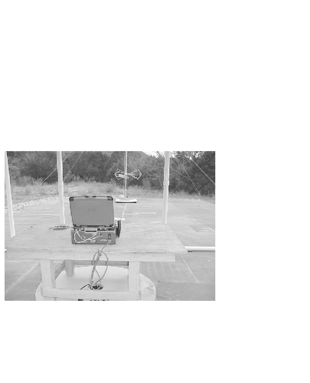
Figure 4.5
A prototype implantable-device programmer is being tested at an open-field test site.
The device sits atop a motorized turntable. A biconical antenna is placed 10 m away from the device
under test.
E
and magnetic-
eld
H
vectors orthogonal to each other but in the same plane. Under these
conditions, electromagnetic propagation occurs as a plane wave.
If the test probe is brought closer and closer to the device under test, however, the nature
of the electromagnetic
fi
fi
field changes. Near the source of the radiation, the
fi
field produced
is mostly a function of the impedance of the source. If the
fi
field is generated by a circuit


Search WWH ::

Custom Search