Biomedical Engineering Reference
In-Depth Information
Glasgow and Aubry
[12]
used disturbance generated by external peristaltic pumps to improve
mixing in a T-junction configuration. The flow rates of the two inlets pulsate with a sinusoidal function.
The best performance was achieved when the two flow rates are 180
out of phase. This confirms the
alternate driving concept used by the systems depicted in
Figs. 7.9, 7.10
, and in sequential
segmentation.
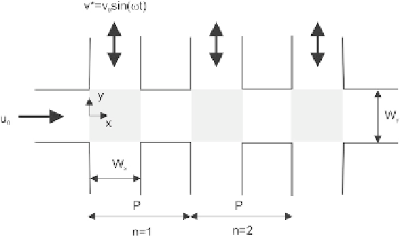
Niu and Lee
[13]
implemented the concept of hydrodynamic instability depicted in
Fig. 7.3
with
multiple side channels. The governing equation
(7.19)
is interpreted as:
(
u
1
W
y
2
d
x
d
t
¼
2
y
=
if
j
y
j <
W
y
=
2
0
if
j
y
j >
W
y
=
2
(
y
n
1
2
o
sin
(7.29)
d
y
d
t
¼
½
2
ð
x
x
c
Þ=
W
x
ð
ut
Þ
if
j
x
j <
x
p
þ
W
x
=
2
0
if
j
x
j >
x
p
þ
W
y
=
2
where
x
c
¼ x
p
þW
x
/2 with
x
p
¼ nP. P
is the length of each mixing unit. All other parameters are
indicated in
Fig. 7.11
. As mentioned previously, the magnitude of the disturbance
y
0
and its angular
frequency
u
are the parameters for the analysis of chaotic advection. In the junction area (gray in
Fig. 7.11
), equation
(7.29)
reduces to:
(
d
x
d
t
¼
u
h
1
2
i
ð
2
y
=
W
y
Þ
(7.30)
d
t
¼ y
n
1
W
x
2
o
sin
2
x
d
y
x
p
Þ=
ðut
Þ:
Following the analysis in
Section 2.4
, particle trajectories can be determined by t
h
e above velocity
field. Using this analysis, an optimal frequency
u
o
and optimal velocity magnitude
y
o
can be chosen
FIGURE 7.11
Hydrodynamic instability with multiple side channels.


Search WWH ::

Custom Search