Biomedical Engineering Reference
In-Depth Information
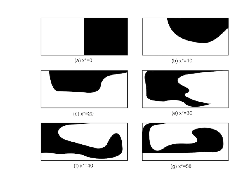
FIGURE 6.20
Concentration distribution along the mixing channel in an SGM. The position is normalized by the channel width
x
) ¼ x/W.
(Redrawn after numerical results of Aubin et al.
[27]
.)
where
a ¼ h
/
H
is the ratio between the ridge height and the channel height, 2
/
Q
is the distance
between the two neighboring ridges,
H
is the channel height, and
W
is the channel width. The
dimensionless variable
h
*
¼ QH
represents the ratio between the channel height and the distance
between two neighboring ridges. The optimal design with the maximum angular displacement change
is achieved with
q ¼
45
and
h
*
p
2.
Jonson et al.
[28]
used an excimer laser to ablate slanted grooves on the bottom wall of the mixing
channel. This structure twists an electrokinetically driven flow into helical stream lines that allows
chaotic mixing at a relatively low velocity of 300
z
m/s. The substrate material of this mixer is
polycarbonate (PC), which is sealed by a cover made of polyethylene terephthalate glycol (PETG).
The mixing channel was 72
m
m
m wide at the top, 28
m
m wide at the bottom, and 31
m
m in depth.
The width of an ablated groove was 14
m
m; the center-to-center spacing between the grooves was
35
m
m. The length of the region occupied by the wells from the T-junction was 178
m
m.


Search WWH ::

Custom Search