Biomedical Engineering Reference
In-Depth Information
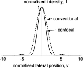
Fig. 6.12
Image intensity for a point object in a conventional microscope (
dashed line
)andin
a confocal microscope with an ideally small confocal pinhole (
solid line
). The Stokes shift is
neglected for a fluorescence system
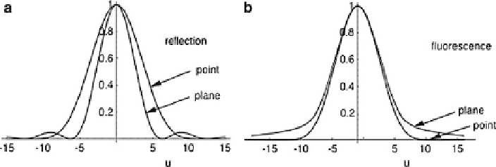
Fig. 6.13
The axial image of point and planar objects: (
a
) in reflection (
b
) in fluorescence
In practice, the confocal pinhole must have some nonzero size in order to detect
enough light. The effect of changing the pinhole size, measured in normalized
coordinates, is shown in Fig.
6.14
. Note that what is important is the size of the
pinhole compared with the spot formed on the pinhole plane, characterized in
Fig.
6.14
by the first zero of the Airy disk, sometimes called 1 Airy unit. The true
size of the pinhole depends on the focal length of the lens used to focus the light
on to the pinhole, which may vary over a wide range for particular systems. In
particular, BioRad systems used a very long focal length lens, thus giving large
pinhole sizes. As the pinhole size is increased, the signal recorded from a point
object increases. With a slit, rather than a pinhole, the signal increases more quickly
with the cross section of the aperture. From the point of view of signal level, there
is no reason to increase the size of the pinhole beyond about
v
d
4, but it is seen
from Fig.
6.14
that by that size the improvement in transverse resolution (for a point
object) of confocal microscopy has disappeared. Also shown in Fig.
6.14
is the axial
resolution (defined so that a bigger number means higher resolution) for a planar
object, either in reflection of fluorescence. The resolution for a fluorescence system
with a slit is also shown. Note that although the signal is higher with a slit than a
Search WWH ::

Custom Search