Biomedical Engineering Reference
In-Depth Information
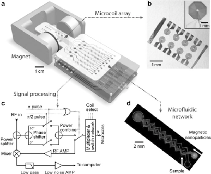
Fig. 9.6
Schematic of microNMR system
.(
a
) The system consists of an array of microcoils for
NMR measurements, microfluidic networks for sample handling and mixing, embedded NMR
electronics, and a permanent magnet for polarizing magnetic field generation. The whole setup
can be packaged as a handheld device for portable operation. (
b
) Micrograph of a microcoil array.
The microcoil (
inset
) generates RF magnetic fields to excite samples and receives the resulting
NMR signal. (
c
) Schematic of the NMR electronics. The circuit is designed to perform T
1
and T
2
measurements via inversion recovery and CPMG (Carr-Purcell-Meiboom-Gill) pulse sequences,
respectively. (
d
) Example of a microfluidic network for effective mixing between magnetic
nanoparticles and the samples (Reproduced from [
22
]. Copyright 2008 Nature Publishing Group)
9.5.1
System Concept
NMR-based cell detection has been previously performed on benchtop relaxometers
(e.g., minispec, Bruker) [
36
,
54
-
56
]. The systems are equipped with permanent, low-
field (<1 T) magnets for field generation, which simplifies operation and housing of
the equipments; however, the main drawbacks of the benchtop system include the
use of relatively large sample volumes (
100L) and the lack of capability for
parallel measurements.
Overcoming these limits, the first NMR prototype was designed and tested for
the feasibility of miniaturization. Figure
9.6
shows the main features of the NMR