Biomedical Engineering Reference
In-Depth Information
Fig. 2.11). The copolymer film is coated on a conducting substrate
(for example, ITO glass or highly doped silicon wafers with a
thermally evaporated gold layer (∼ 50 nm)), which forms one
electrode contact. A 25 μm thick polyimide foil (Kapton CR, DuPont)
with a 50 nm thermally evaporated Au layer on the reverse side
makes a convenient counterelectrode and dielectrically strong
insulating layer for the capacitor (to prevent breakdown at high
fields). Conformal contact with the polymer layer is acheived using
a thin layer (∼2 μm or more) of cross-linked poly(dimethylsiloxane)
rubber (PDMS, Sylgard 184, Dow Corning) coated on the front
side of the Kapton sheet. A constant voltage of up to 4 kV is
applied across the assembled layer while heating above the glass
transistion temperature of both components, and removed after
cooling to room temperature (where the microphase is frozen in
place in the glassy polymer matrix). The counterelectrode is peeled
away from the copolymer film, allowing subsequent etching of the
minority component.
February 8, 2010 17:21
(a)
(b)
(c)
pt counter electrode
freestanding nanowire array
au
kapton
PDMS
perforated PFS Matrix
3-
4
kV
au
v
silicon
au
replicated
nanowires
working electrode
(d)
(e)
(f)
200 nm
200 nm
200 nm
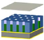
Figure
Schematic illustration of freestanding nanowire array
fabrication from electric-field-aligned, sacrificial cylinder-forming block
copolymer films. (a) Annealing of copolymer film above glass transition
temperatures in a parallel-plate capacitor geometry with applied electric
field. (b) Voids left by removal of the minority phase are electrochemically
replicated from the underlying conducting substrate. (c) The supporting
template is removed by UV ozone etching to leave a freestanding nanowire
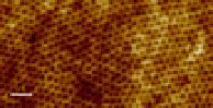
array. (d) Tapping mode atomic force microscopy (height image) of a porous
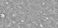
PFS template after PLA removal. (e) Surface SEM of the electrochemically
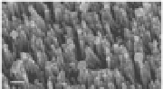
filled template. (f) Freestanding nanowires (Cu
2.11
O/Cu mixed phase) after UV
ozone etching of PFS matrix. Reproduced from Ref. [54] by permission of
the Royal Society of Chemistry.
2


Search WWH ::

Custom Search