Environmental Engineering Reference
In-Depth Information
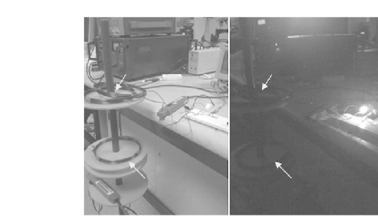
Load and
Receiving
Coils
Load and
Receiving
Coils
Light
Bulb
Lightbulb
Source and
Transmitting
Coils
Source and
Transmitting
Coils
FIGURE 6.24
Demonstration of wireless power transmission of watt level.
and 2 of different dimensions tuned to the same frequency by adjusting their
capacitances based on the fundamental equation given by
Equation 6.2
.
Both
the LED and lightbulb loads were lit with the same WPT source, and this
exhibited the capability of the WPT system to transfer power to multiple elec-
trical devices in a wireless manner. Another interesting observation to note
from
Figure 6.25
is that the smaller coil (i.e., load and receiving coil 1), placed
on the table was out of the source coil's line of sight, but magnetic waves were
still able to power the load without interacting with the extraneous objects,
such as the wood and steel of the table, between the transmitting and receiv-
ing coils. This is one of the unique advantages of using resonant magnetic
waves as they do not interact with nonmagnetic materials such as plastic and
wood. Even if there was magnetic material between the transmitting and re-
ceiving coils, as can be seen in
Figure 6.25
, where load and receiving coil 1
is placed on the table made of wood and steel, energy was still able to be
transferred wirelessly to the LED load 1. This is because the fundamental
TABLE 6.2
Efficiency of WPT System Powering Different Lightbulbs
Bulb
Distance
Rating (V)
(cm)
V
in
(V)
I
in
(A)
V
out
(V)
I
out
(A)
P
in
(W)
P
out
(W)
WPT
(%)
2.4
15
5.9
0.12
1.05
0.32
0.708
0.336
47.5
2.4
20
6.5
0.28
1.64
0.39
1.820
0.640
35.2
3.6
20
7.2
0.29
2.05
0.39
2.088
0.800
38.3
7.2
20
8.1
0.26
2.40
0.35
2.106
0.840
39.9
12
20
8.5
0.25
3.17
0.34
2.125
1.078
50.7


Search WWH ::

Custom Search