Environmental Engineering Reference
In-Depth Information
Signal Generator
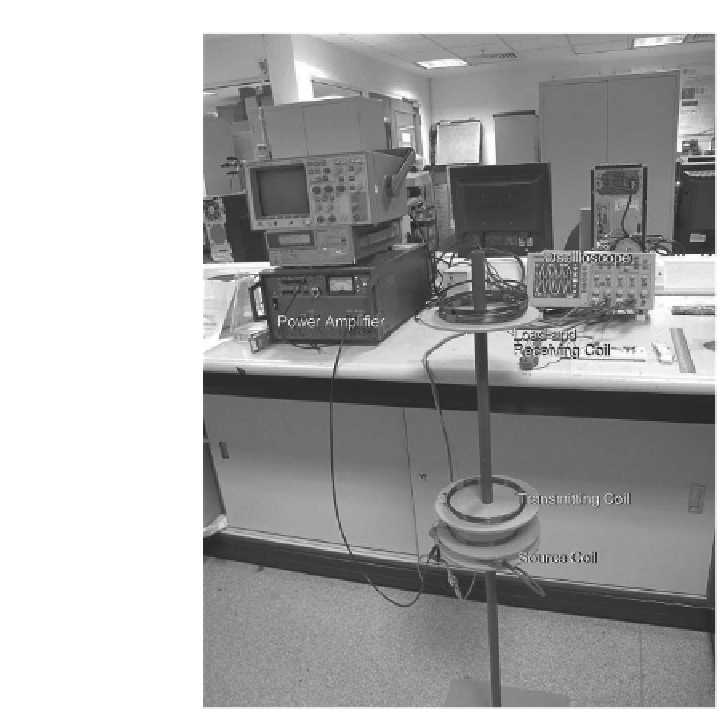
FIGURE 6.23
Experimental setup of the WPT system.
P
in
at the source coil, output power
P
out
at the load coil, and efficiency
WPT
of the WPT system, are recorded in
Table 6.2
.
Referring to
Table 6.2
, it can be observed that the output power and effi-
ciency of the WPT system for different loading conditions (i.e., 2.4 to 12-V
lightbulbs) ranged between 0.6 and1Wand 35% to 50%, respectively. One
interesting observation to note from
Table 6.2
is that for the 2.4-V lightbulb,
as the distance between the coils was reduced from 20 to 15 cm, the WPT
efficiency increased by more than a third to around 47.5%. This positive ob-
servation is in line with the conclusion from the discussion of simulation
in Section 6.2.2. Once the one-to-one WPT system was investigated, the fol-
lowing experiment shown in
Figure 6.25
was designed to demonstrate the
concept of powering multiple devices, that is, LED load 1 and lightbulb load
2ofdifferent geometries operating at the same resonant frequency.
With reference to
Figure 6.25
, it can be seen that a single source and trans-
mitting coil were able to power up two separate load and receiving coils 1


Search WWH ::

Custom Search