Environmental Engineering Reference
In-Depth Information
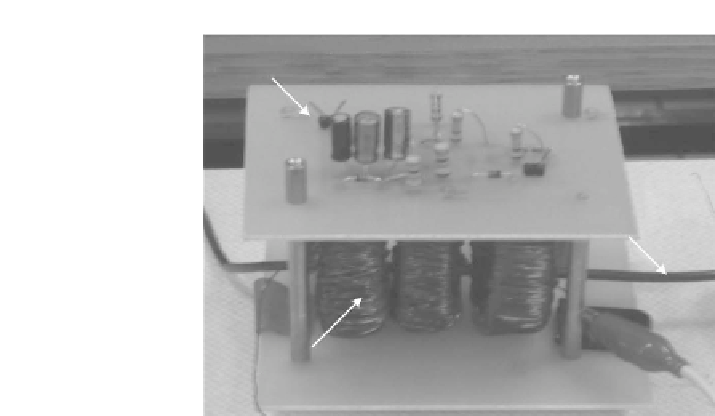
Power Management Unit (Voltage Doubler,
Energy Storage, and Voltage Regulator Circuits)
Power Line
Carrying AC
Current
Inductive Coil
Windings
FIGURE 6.8
Photograph of the magnetic energy harvester system powering the wireless RF transmitter.
Based on the electrical power requirements of the wireless RF transmit-
ter and the electrical characteristic of the magnetic energy harvester (i.e.,
N
,
, and
B
), a magnetic energy harvesting prototype has been designed and
successfully implemented. The schematic drawing of the prototype of the
magnetic energy harvesting system is shown in
Figure 6.9
. The prototype
was designed to be similar to a transformer secondary winding capable of in-
ducing AC voltage from the current-carrying conductor single-turn primary
winding to power up a wireless RF transmitter. The induced
V
emf
was first
rectified to DC voltage using a voltage doubler. Once the voltage from the
secondary coil of the transformer was rectified, the electric current would
flow to charge the electrolytic storage capacitor C1 of the power storage and
supply circuit. The Q1 and Q2 metal-oxide-semiconductor field-effect tran-
sistors (MOSFETs) residing in the power storage and supply system acted
like a control switch that would initiate an on or off signal to the storage
capacitor to release the stored energy. Initially, both Q1 and Q2 were off, so
the ground lines of the linear regulator (MAX666) and the RF AM transmitter
(RTFQ1-433) were disconnected from C1. As C1 charged beyond the preset
voltage of around 6.8 V (the preset voltage level was determined according to
zener diode Z1 as 6.2 V and the gate-source junction of Q1 as 0.6 V), the con-
trol switch Q1 turned on. The moment when Q1 was on, there was a voltage
drop across R2 that was higher than the threshold gate-source voltage
V
gs
(
th
)
of Q2 in order to activate the control switch Q2. Once Q2 was activated, Q1
was latched. This connected the ground lines of MAX666 and AM-RTFQ1-
433 with C1, allowing C1 to discharge through the circuitry. MAX666 acted
like a low power series linear regulator, which produced a stable +3.3 V for
the serial ID encoder (HT12E) and the RF AM transmitter (AM-RTFQ1-433)


Search WWH ::

Custom Search