Information Technology Reference
In-Depth Information
oversampled by a factor of two because they are half empty. As a result both can be decimated by a factor of two,
resulting in (d) in two identical Nyquist-sampled frequency bands of half the original width.
An inverse QMF will recombine the bands into the original broadband signal. It is a feature of a QMF/inverse QMF
pair that any energy near the band edge which appears in both bands due to inadequate selectivity in the filtering
reappears at the correct frequency in the inverse filtering process provided that there is uniform quantizing in all the
sub-bands. In practical coders, this criterion is not met, but any residual artifacts are sufficiently small to be
masked.
The audio band can be split into as many bands as required by cascading QMFs in a tree. However, each stage
can only divide the input spectrum in half. In some coders certain sub-bands will have passed through one splitting
stage more than others and will have half their bandwidth.
[
8
]
A delay is required in the wider sub-band data for time
alignment.
A simple quadrature mirror is computationally intensive because sample values are calculated which are later
decimated or discarded, and an alternative is to use polyphase pseudo-QMF filters
[
9
]
or wave filters
[
10
]
in which the
filtering and decimation process is combined. Only wanted sample values are computed. In a polyphase filter a set
of samples is shifted into position in the transversal register and then these are multiplied by different sets of
coefficients and accumulated in each of several phases to give the value of a number of different samples between
input samples. In a polyphase QMF, the same approach is used.
Figure 3.26
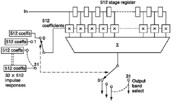
shows an example of a 32-band polyphase QMF having a 512-sample window. With 32 sub-bands,
each band will be decimated to 1
32
of the input sampling rate. Thus only one sample in 32 will be retained after the
combined filter/decimate operation. The polyphase QMF only computes the value of the sample which is to be
retained in each sub- band. The filter works in 32 different phases with the same samples in the transversal
register. In the first phase, the coefficients will describe the impulse response of a low-pass filter, the so-called
prototype filter, and the result of 512 multiplications will be accumulated to give a single sample in the first band. In
the second phase the coefficients will be obtained by multiplying the impulse response of the prototype filter by a
cosinusoid at the centre frequency of the second band. Once more 512 multiply accumulates will be required to
obtain a single sample in the second band. This is repeated for each of the 32 bands, and in each case a different
centre frequency is obtained by multiplying the prototype impulse by a different modulating frequency. Following 32
such computations, 32 output samples, one in each band, will have been computed. The transversal register then
shifts 32 samples and the process repeats.
Figure 3.26:
In polyphase QMF the same input samples are subject to computation using coefficient sets in many
different time-multiplexed phases. The decimation is combined with the filtering so only wanted values are
computed.
The principle of the polyphase QMF is not so different from the techniques used to compute a frequency transform
and effectively blurs the distinction between sub-band coding and transform coding.
[
7
]
Jayant, N.S. and Noll, P.,
Digital Coding of Waveforms: Principles and applications to speech and video
.
Englewood Cliffs, NJ: Prentice Hall (1984)
[
8
]
Theile, G., Stoll, G. and Link, M., Low bit rate coding of high quality audio signals: an introduction to the MASCAM
system.
EBU Tech. Review
, No. 230, 158-181 (1988)
[
9
]
Chu, P.L., Quadrature mirror filter design for an arbitrary number of equal bandwidth channels.
IEEE Trans.
ASSP
,
ASSP-33
, 203-218 (1985)
[
10
]
Fettweis, A., Wave digital filters: Theory and practice.
Proc. IEEE
,
74
, 270-327 (1986)