Graphics Programs Reference
In-Depth Information
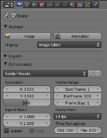
Figure 17.12
17.3.2 Fluid Object Setup
In this scenario, there is no fluid object; instead, we use an in-
flow object (the sphere) to provide a continuous flow of fluid.
17.3.3 Inflow Object Setup
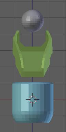
Make particular note of the scale of the inflow object relative to
the obstacle objects; the scale of the inflow object determines
the physical volume of the fluid in the scene (Figure 17.13). If
the inflow object is too large, the volume of fluid will spill over
the sides of the trough and cup.
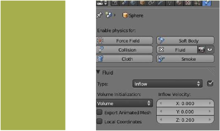
With the inflow object selected in the 3D window, go to
the properties window - “Physics” button - “Fluid” tab. Since
the domain object has been previously set, the “Fluid” options
in the “Type” tab should already be available. Select “Inflow”
to display the inflow options (Figure 17.14). To give the fluid
a small amount of momentum, set the “Z” initial velocity at
0.20. In doing this, the fluid will move before the acceleration
due to the effects of gravity. Leaving the “Z” velocity at 0 pro-
duces a rather sluggish fluid flow.
Change value to 200.
17.3.4 Obstacle Object Setup (Trough)
Make particular note of the construction of the trough; it has been modeled by extruding
and scaling a cube into a rectangular U shape, rotated to provide an incline, and positioned
Figure 17.13
Figure 17.14