Graphics Programs Reference
In-Depth Information
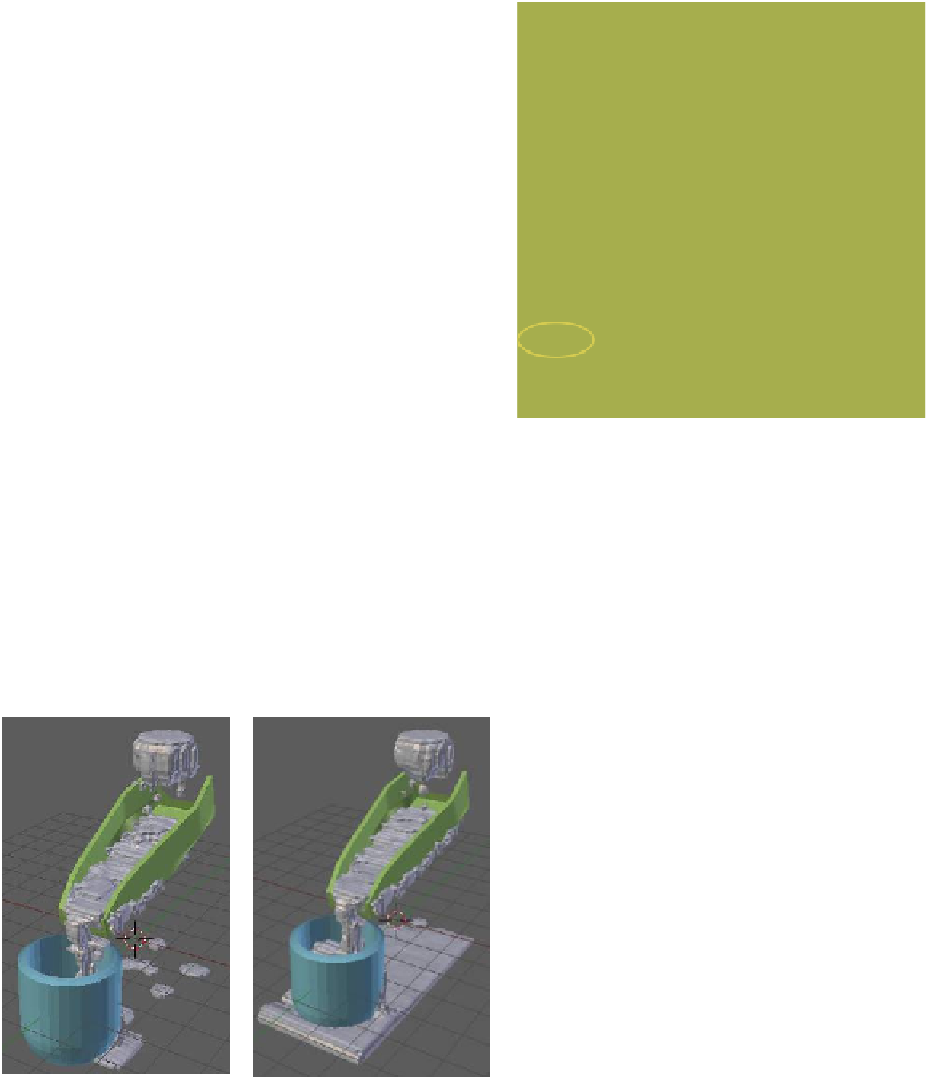
below the inflow object and above the cup. In this dem-
onstration, the trough construction does not have to be
exactly as shown in the diagrams. Start with a cube object
and scale it along the
x
-axis. Tab into edit mode and turn
off “Limit selection to visible” in the 3D window header.
In end view, progressively select vertices to form a cube
face and extrude, as shown in Figure 17.9(right). You
can modify the profile as you wish (scale the ends of the
trough to fit the cup and inflow), then when completed
tab back to object mode and add a subdivision surface
modifier. Without the modifier, the fluid tends to break
through the trough surface.
With the trough constructed, select it in the 3D
window, go to the “Fluid” tab, and select “Obstacle”
(Figure 17.15). Set the “Volume Initialization” option
to “Shell” and the “Slip Type” to “Free.” The “Volume
Initialization” and “Shell” options initialize a thin lay-
er for all the faces of the mesh, which prevents fluid
breakthrough. The “Free” option allows fluid move-
ment along the obstacle. For other options, see the
Blender Wiki manual.
Figure 17.15
Figure 17.16
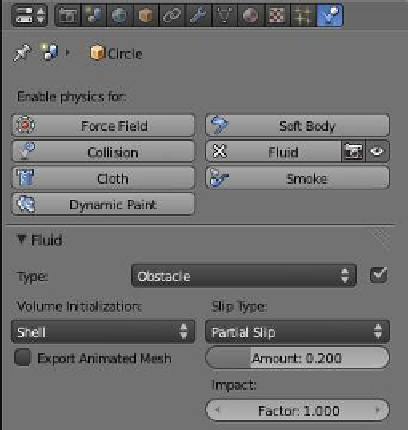
17.3.5 Obstacle Object Setup (Cup)
The model of the cup is identical to that used in the
first scenario. Set the value options the same as for the
trough obstacle object, except set the “Volume Initial-
ization” option to “Shell” and the “Slip Type” to “Partial
Slip” (Figure 17.16). All objects included in the simulation
Note
: In these examples, fluid is seen breaking
through the trough and cup. Applying a
subdivision surface modifier to the trough and
cup mesh and increasing the “Resolution” -
“Final” value in the “Physics” - “Fluid” tab will
resolve this.
Figure 17.17
Frame 30
Frame 80