Graphics Programs Reference
In-Depth Information
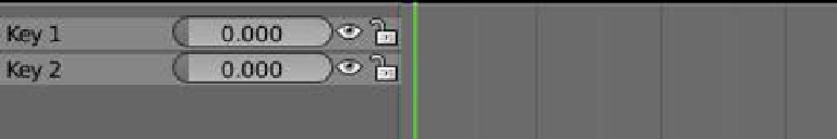
Figure 16.6
“Key 2” has been added to the shape key editor.
Figure 16.7
Orange diamond shapes
Cursor at frame 1
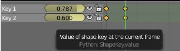
Figure 16.8
Cursor at
new frame
key editor; by doing so, a key frame is automatically inserted at the frame where the cur-
sor is located. In the properties window - “Shape Key” tab, click on the + sign again to
add “Key 2” (Figure 16.4). In the 3D window, tab to edit mode, select a different vertex,
and move it somewhere to set the limit of movement (Figure 16.5). Tab back to object
mode and you'll notice that “Key 2” has been added to the shape key editor (Figure 16.6).
In the shape key editor, move each slider to see the plane change shape in the 3D win-
dow, then return each slider to the 0.000 position. Moving the sliders has inserted key
locations in the timeline of the shape key editor at frame 1, as indicated by the orange
diamond shapes (Figure 16.7). Drag the green line to a new frame, move the key sliders
(to 0.787 and 0.600, respectively). New key frames are inserted, marked again by orange
diamond shapes (Figure 16.8). Scrub the timeline (drag the green line) to see the anima-
tion. You can also press Alt + the A key with the cursor in the 3D window to play the
animation, and Esc to stop.
16.3 Action Editor
To demonstrate the action editor, begin with the same setup as you used for the shape key
editor, except this time select “Action Editor” mode in the dope sheet window. Select the
plane in the 3D window in object mode and insert a key frame (with the I key) and select
“LocRotScale.”
In the dope sheet action editor, you will see the key frame displayed in the upper LHS of
the window. Clicking on the little triangle in front of “LocRotScale” expands the key frame
to show the individual components (Figure 16.9). In the action editor window header, click
on “View” and tick “Show Sliders”; there are now value sliders in each component of the key