Graphics Programs Reference
In-Depth Information
12.4.7 Mesh Deform Modifiers
The mesh deform modifier can deform one mesh with
another cage mesh. This is similar to a lattice modifier
but instead of being restricted to the regular grid lay-
out of a lattice, the cage can be modeled to fit around
the mesh object being deformed. The cage mesh must
form a closed cage around the part of the mesh to be
deformed, and only vertices within the cage will be de-
formed. Typically the cage will have far fewer vertices
than the mesh being deformed.
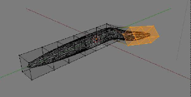
After modeling a UV sphere mesh object, surround
it with a simple cage mesh by scaling a cube to it
around the elongated sphere then selecting vertices in
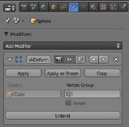
edit mode and extruding them. Apply a mesh deform
modifier to the scaled UV sphere. Enter the name of the
cage mesh and press “Bind” to link the two meshes. The
“Bind” operation may take several seconds to calculate
depending on the complexity of your model. Wait until
“Bind” changes to “Unbind” before selecting vertices on
the cage (Figure 12.67). By dragging, scaling, and rotating the selected vertices, the original
mesh will be deformed (Figure 12.68). The proximity of the cage to the original object has
an influence on how the deformation reacts.
Click on “Bind” and wait until it
changes to “Unbind.”
Figure 12.67
Note:
The cage mesh will render in the scene; therefore, with the cage surrounding
the elongated sphere, all you will see is the cage. You can select the cage and move it
away from the sphere, keeping the deformation, but the cage will still render. To see
the elongated sphere deformed without the cage, click on “Apply” in the modifier tab.
The modifier is applied to the sphere and removed. You can now delete the cage and
the elongated sphere remains deformed.
The UV sphere is scaled along
the x-axis to form an elongated
worm shape.
Part of the cage is selected, moved,
and rotated to deform the sphere.
The cube is extruded to form
a cage.
Wireframe viewport shading
Figure 12.68