Biomedical Engineering Reference
In-Depth Information
(a)
(b)
200
(c)
150
100
50
0
-
50
18
20 22
Depth below coverslip (
µ
m)
24
26
28
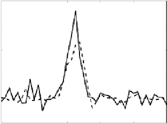
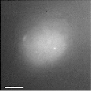
Figure 15.14
Images of green luorescent protein (GFP)-TRF1-labeled telomeres in UMUC bladder cancer cells.
(a) Uncorrected images 23 μm below the coverslip. (b) Depth aberration corrected 23 μm below the coverslip. he
correction assumed a sample index of 1.38. (c) Background subtracted proiles through the labeled telomere (bright
spot in images a and b) along the axial direction. he dashed line is from the uncorrected image (a), and the solid
line is from the corrected image (b). he peak intensity in the corrected image is 60% larger over the background.
he scale bar is 5 μm (Kner et al., 2010).
mentioned above, that in wide-ield microscopy aberrations afect point sources and larger structures
diferently. For example, the intensity of a uniform distribution of luorescent molecules will not be
afected by aberrations. Because the efect of aberrations on the intensity is not linear, the intensity may
not increase if aberrations remain, even if some aberrations have been corrected. hus, the expected
change in intensity from complex biological samples can be hard to predict.
Figure 15.15
shows another example: GFP-labeled centromeres in eye imaginal discs in
Drosophila
larvae. In this sample, correcting the depth aberration did not increase the intensity of the signal from
the GFP centromeres, possibly because of the strong efects of scattering, but the FWHM of the centro-
mere images in the axial direction is smaller by 27%, which can be seen in
Figure 15.15
.
15.3.2 Focusing
If Equation 15.2 is used instead of Equation 15.1 to set the wavefront, the DM will focus into the sample.
An example of focusing through the sample is shown in
Figure 15.16
.
DM is an attractive option for
focusing through the sample quickly without perturbation. Mechanical movement of either the sample
or the microscope objective could potentially disturb the sample through the acceleration and the move-
ment of the immersion oil. DMs, depending on the technology, can be set in less than a millisecond,
whereas mechanical focusing typically takes several milliseconds. But focusing with the DM requires a
much larger wavefront adjustment. Imaging 20 μm into an aqueous sample at NA 1.25 requires a 16.7 μm
peak-to-valley wavefront for focusing and a 4.0 μm adjustment for correcting only depth aberrations with
an oil-immersion objective. he large correction for focusing means that the amount of focusing that can
be achieved is limited by the DM throw. More importantly, any inability of the mirror to replicate the
exact shape will lead to a residual wavefront error that will reduce the Strehl ratio of the corrected image.