Biomedical Engineering Reference
In-Depth Information
CCD
Lenslet
Wavefront
θ
∆
s
F
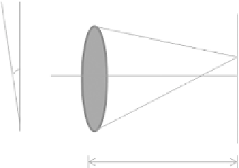
FIGuRE 9.14
Wavefront.measurement.of.a.single.lenslet.
he. Shack-Hartmann. WFS. reconstructs. the. wave. aberration. based. on. the. displacements. of. the.
focused.Shack-Hartmann.spots.from.the.reference-spot.positions.for.a.perfect.wavefront.(Figure 9.14)..
he.slope.of.the.wavefront.(θ).is.given.by.spot.displacement.Δ
s
.as.in.Equation.9.7:
θ =
∆
s
F
.
.
(9.7)
where.
F
. is. the. focal. length. of. the. lenslet.. Measurement. accuracy. of. the. wavefront. sensor. is. directly.
related.to.the.precision.of.the.measurement.of.Δ
s
..he.lenslet.and.the.CCD.camera.should.be.mounted.
and.aligned.permanently.as.an.optical.subassembly..Align.the.lenslet.array.and.the.CCD.camera.with.a.
well-collimated.wavefront..he.incoming.alignment.beam.should.be.perpendicular.to.the.CCD.camera.
and.the.tilt.of.the.camera.with.respect.to.the.alignment.beam.must.be.minimized.to.achieve.the.maxi-
mum.dynamic.range.for.the.wavefront.measurement.
Adjust.the.tip.and.tilt.angles.so.that.the.retrorelection.from.the.CCD.is.relected.back.through.the.
optics. to. the. source. of. the. alignment. beam.. hen. insert. the. lenslet. array. in. the. beam. and. adjust. the.
lenslet.array.positions.laterally.and.longitudinally.so.that.the.array.is.centered.and.the.focused.spots.on.
the.CCD.camera.are.as.sharp.as.possible..Adjust.the.tip.and.tilt.angle.so.that.the.retrorelection.from.
the.lenslet.array.and.the.CCD.camera.are.going.back.to.the.incoming.laser.source..Fine-tune.the.lenslet.
array.positions.both.laterally.and.longitudinally.until.the.focused.spots.on.the.CCD.are.as.sharp.as.pos-
sible..Finally,.ix.the.relative.position.between.the.lenslet.array.and.the.CCD.camera.and.integrate.the.
two.components.together.as.one.optical.subassembly..he.centered.spots.provide.the.reference.spots.of.
the.Shack-Hartmann.WFS,.while.the.displacement.of.the.focused.spots.from.the.reference.spots.can.be.
used.to.reconstruct.the.wavefront.aberrations.
9.7.3 Pupil Plane camera
AO.biological.imaging.systems.achieve.high-resolution.by.using.AO.to.compensate.for.the.aberrations.
in.the.optical.beam..In.a.properly.aligned.AO.optical.microscope,.the.pupil.for.eyepieces.in.the.micro-
scope,.the.lenslet.array.in.the.Shack-Hartmann.WFS,.and.the.DMs.should.be.simultaneously.in.focus.
to. ensure. the. correct. measurement. and. compensation. of. optical. aberrations.. In. addition,. if. there. are.
scanners. involved,. the. scanner. should. be. placed. at. the. conjugate. planes. with. the. DMs. and. WFS,. so.
that.the.image.of.the.DM.on.the.WFS.is.quasi-static,.which.means.the.image.does.not.move.around.as.
a.function.of.time.
Typically. a. pupil. camera. is. placed. in. the. optical. beam. to. help. with. the. alignment. process.. Since.
the pupil. for. eyepieces. in. the. microscope,. the. lenslet. array. in. the. Shack-Hartmann. WFS,. the. DMs,.
and.the.scanners.are.at.conjugate.planes,.their.images.should.all.be.in.focus.and.superimposed.on.the.
camera.


