Biomedical Engineering Reference
In-Depth Information
It.may.be.confusing.to.interpret.what.we.see.on.the.camera.when.several.images.show.up.together,.
and.it.is.also.diicult.to.tell.if.the.images.are.in.focus..One.method.is.to.place.a.test.target.or.iducial.
mark.on.the.component.and.observe.if.we.see.a.clear.image.of.the.test.target.on.the.camera..Quite.oten,.
there.are.some.dust.particles.or.sharp.edges.on.the.surface.of.the.optical.component..hese.can.be.help-
ful.to.judge.if.the.component.is.in.focus.as.well.
Start.with.the.optical.component.closest.to.the.pupil.camera.and.block.all.other.components.in.the.
optical.path..If.that.is.not.possible,.block.half.of.the.beam.so.that.an.image.of.the.other.half.of.the.com-
ponent.is.viewed..If.the.image.is.not.clear.on.the.camera,.move.the.component.longitudinally.until.the.
image.is.in.sharp.focus..hen.repeat.the.procedure.with.the.next.optical.component.along.the.optical.
beam.path.until.all.the.conjugate.components.show.up.clearly.in.the.pupil.plane.camera..Typically,.only.
small.adjustments.for.the.positions.of.the.optical.components.are.needed.
Even.though.the.pupil.camera.is.not.a.part.of.the.AO.science.imaging.system,.it.is.recommended.to.
keep.it.permanently.in.the.system.to.use.as.a.diagnostic.tool.for.troubleshooting.and.calibration.of.the.
AO.system.
9.7.4 Photomultiplier tube Pinhole Adjustment
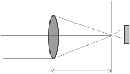
he.photomultiplier.tube.(PMT).subassembly.consists.of.a.high-quality.focusing.lens,.a.pinhole,.and.a.
science.camera,.as.shown.in.Figure.9.15..he.pinhole.is.a.critical.element.to.achieve.difraction-limited.
images..he.diameter.of.the.pinhole.
d
.is.determined.by.Equation.9.8:
λ
F
D
.
d
=
2 44
.
.
(9.8)
where.λ.is.the.wavelength,.
F
.is.the.focal.length.of.the.lens,.and.
D
.is.the.diameter.of.the.optical.beam.
he.pinhole.adjustment.may.be.challenging.to.those.who.are.not.skilled.in.the.art..Start.with.a.pin-
hole.size.several.times.larger.than.what.is.required.for.the.best.image.quality..Either.the.focusing.lens.
or.the.pinhole.needs.to.be.placed.on.a.
x
,.
y
,.
z
.translation.stage.with.micrometer.adjustment.accuracy..
Illuminate. the. PMT. with. a. collimated. optical. beam;. place. the. pinhole. close. to. the. focal. plane. of. the.
lens.by. measuring. the.distance. between.the.pinhole. and.the.lens;.and.adjust.the.
x
,.
y
.positions. of. the.
pinhole.with.the.micrometers,.until.the.science.camera.receives.some.photons,.and.images.show.up.on.
the.computer.screen..Fine-tune.the.
x
,.
y
.positions.so.that.the.image.is.brightest.for.the.axial.
z
.position..
Slightly.increase.the.distance.between.the.focusing.lens.and.the.pinhole.by.adjusting.the.micrometer.
for.axial.adjustment..Repeat.the.above.procedures.with.the.
x
,.
y
.position.adjustment..hen.increase.the.
axial.distance.between.the.focusing.lens.and.pinhole.and.repeat.the.same.process..When.the.maximum.
Pinhole
Focusing
lens
PMT
F
FIGuRE 9.15
PMT.subassembly.