Biomedical Engineering Reference
In-Depth Information
1
3
1
3
2
(a)
4
2
(b)
4
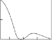
FIGURE 2.17
(a) Simple changeover point and (b) 2 × 2 optical cross point.
state, 1 is connected to 4 and 2 is connected to 3. This crossed state may be
achieved by mechanical means such as by physically moving the fiber or a
prism into the optical path. If the waveguide is made from a material such
as LiNbO
3
, however, then the crossing may be caused by applying a voltage
and utilizing the electro-optic effect. The latter is obviously preferred due
to difficulties in aligning microfibers, prisms, etc., in a mechanical setup.
Currently, typical LiNbO
3
switches have insertion losses of 3-5 dB, extinc-
tion ratios of 20-30 dB, and require control voltages of 2-30 V depending on
switching speed. For mechanical microoptic devices, these values would
be 1.5 dB, >60 dB, and 14 V, respectively [40]. The cost of each type of device
is roughly the same; however, LiNbO
3
switches are rapidly evolving, and
improved device performance as well as greater reliability and lower cost
will push the balance in favor of that technology.
2.3.2 Directional Couplers
The basic directional coupler shown in Figure 2.18 [41] consists of two iden-
tical single-mode channel waveguides fabricated in close proximity via Ti
diffusion over a length
L
. This allows synchronous coupling between the
overlapping evanescent mode tails. Typical values of
L
are on the order of
1-10 mm. If the velocity of propagation is the same in both guides (same
v
1
3
1.0
2
4
L
(
)
P4
P1
v
0.5
+
-
Guide
2
E
0.0
1
2
3
4
Guide
1
∆β
L
TT
(a)
(b)
FIGURE 2.18
(a) Directional coupler and (b) transfer characteristic.


Search WWH ::

Custom Search