Biomedical Engineering Reference
In-Depth Information
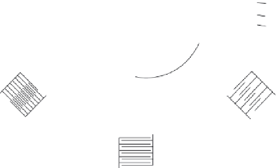
Low
frequency
Input
light
High
frequency
High
frequency
transducer
Low
frequency
transducer
FIGURE 3.9
Angular staggered-tilted transducer array.
substrate. Another approach is the stagger-tilted array, where each element
is tilted slightly to be optimized for its segment of the system bandwidth
[17]. Figure 3.9 illustrates this method. The electrical impedance of a typical
transducer array is about 9 Ω. The impedance of the driving electronics is
50 Ω, so there must be an impedance-matching transformer of some kind at
the transducer interface.
3.3.1 Fourier Transform, Fourier Transform Lens
The function of the Fourier Transform lens is to rearrange the diffracted light
beam output from frequency-dependent Bragg angles to frequency-dependent
positions, so that the output of the PD array is a linear distribution of frequen-
cies. The light output, or what the PDs see is three sin
c
functions [18]:
⎡
⎤
c
lx
F
m
⎛
⎝
x
F
m
x
F
⎞
⎟
⎛
⎜
⎞
⎟
+
⎛
⎜
⎞
⎟
f
f
f
(
)
sin
sin
sin
u x
=
k
+
cl
−
f
cl
+
f
⎥
(3.4)
⎢
⎜
f
λ
2
λ
2
λ
⎣
⎦
where
x
f
is the position of the spot
l
is the AO aperture
m
is the grating modulation depth or RF signal level
f
is the reciprocal of the diffraction grating spacing or 1/Λ
k
is a constant that accounts for the laser light output and the system's opti-
cal losses
F
is the distance between the lens and the focal plane or PD array


Search WWH ::

Custom Search