Biomedical Engineering Reference
In-Depth Information
The efficiency is stated in percentage per Watt of RF drive. Typical bulk dif-
fraction efficiencies are 29%/W at 1.1 GHz, and 105%/W at 350 MHz, both for
GaP cells.
SAW diffraction efficiencies are higher, such as 200%/W around 600 MHz,
but the optical losses are higher. Equation 3.3 assumes the piezoelectric
transducer is of the interdigital type that emits surface acoustic waves. The
interdigital elements couple the electric excitation field directly onto a piezo-
electric material. The elements are metal-deposited onto the AO material.
The light at the output of a Bragg cell is not entirely diffracted. For exam-
ple, using a typical RF input power of 100 mW and the 200%/W SAW dif-
fraction efficiency mentioned previously, the diffracted light would be
200%/W × 0.1 W = 20%, with 80% of the light undiffracted (or zeroth order).
The desired light output is either of order 1, in the case of upward Doppler
shifting, or −1, for downward Doppler shifting. A PD is usually put at the
zeroth order focal point, after the Fourier Transform lens, to absorb energy
and to act as a built-in test device for monitoring the laser output.
Referring back to Equation 3.3, it is obvious that the Bragg angle changes
with the RF operating frequency. In early receiver designs, the Bragg angle
was optimized for the center frequency, but the Bragg cell became very inef-
ficient as the input frequency moved away from the center. The bandwidth
of the Bragg cell is determined by the acoustic radiation pattern of the trans-
ducers. The bandwidths of modern receivers approach an octave, so there
are several things that can be done to maintain good AO efficiency over a
wider bandwidth. The interaction length can be decreased, but the AO effi-
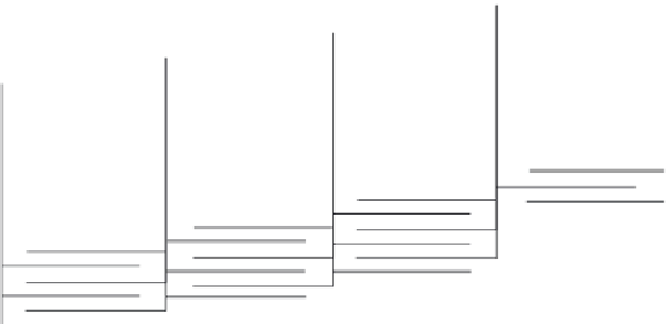
ciency also drops. More commonly, the transducers are designed as a phased
array, with each element staggered forward as the light travels across the
Bragg cell. Figure 3.8 illustrates this [16]. This works quite well with IO Bragg
cells, especially those made with LiNbO
3
, which is a strong piezoelectric
material. The interdigital elements can easily be deposited directly onto the
Steering array
of interdigital
transducers
Acousto-optic
cell
FIGURE 3.8
Staggered transducer array.

Search WWH ::

Custom Search