Biomedical Engineering Reference
In-Depth Information
plane of the microscope objective. As we can see from the scheme, the DOE is placed in a conjugate optical
plane with respect to the back focal plane of the objective and to the two galvo-mirrors. Three telescopes
are optically relaying the DOE with the X scanner (L1,L2), one scanner with the other (L3,L4), the scan-
ning head with the objective (L5,TL). With this configuration, while a single beam of the grid has the same
profile than in a single-beam scanning microscope, the grid profile is focused on both scanners and on the
objective back focal plane, in order to provide a beam spacing in the focal plane and hence to scan adjacent
points. The spacing of the beams in the grid is set by the magnification of the telescope formed by the tube
lens and the microscope objective. To provide simultaneous acquisition of multiple scanned points, the
emitted signal is detected by means of a CCD camera or a photomultiplier array. By means of this multi-
spot arrangement for scanning operation, SHG images can be recorded with the same resolution and the
same SNR in a time which is reduced by a factor
n
2
with respect to the equivalent single-beam scanning.
2.2.8 An SHG Holographic Microscope
As shown in the previous sections, in the most general case, SHG microscopy is based on the scanning
of femtosecond-pulsed beams, tightly focused by high numerical aperture objectives. However, this is
not the only optical configuration that can be used when designing an SHG microscope. In fact, another
relevant solution can be adopted taking advantage of the coherent nature of the optical process gener-
ating second harmonic. Such alternative is represented by holographic second-harmonic generation
microscopy (Shaffer et al., 2010, Masihzadeh et al., 2010).
The combination of SHG microscopy and holographic imaging acquisition provides a powerful com-
bination for improving imaging speed. The principle of operation is quite similar to digital holographic
microscopy; the only difference is that second harmonic, instead of the scattered light, interferes and
creates the hologram. Since holography encodes 3D optical field information in single 2D images, it
enables the sample to be imaged in three dimensions at vastly improved speeds (typically in the order
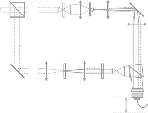
of ms/scan). The optical system used is analogous to a Mach−Zender interferometer (see Figure 2.12). A
beam-splitter cube (BS) divides the excitation beam in two separate arms: the reference arm (R) and the
Laser
O
M
FL
BS
BE
FDC
C
S
MO
R
BS
M
L
FDC
L
F
BE
F
CCD plane
d
CCD
I = 400 nm
I = 800 nm
Image plane
FIgurE 2.12
Experimental setup schematics for an SHG holographic microscope. BS, beamsplitter cube; BE,
beam expander; C, condenser lens; S, sample; MO, microscope collection objective; M, mirror; FL, field lens; F,
filter; L, lens and FDC; nonlinear crystal.
O
designates the object arm, while
r
designates the reference arm. d is the
hologram reconstruction distance. (From Shaffer, E., Marquet, P. and Depeursinge, C. 2010. Real time, nanometric
3D-tracking of nanoparticles made possible by second harmonic generation digital holographic microscopy.
Opt.
Express,
18: 17392-17403. With permission of Optical Society of America.)