Biomedical Engineering Reference
In-Depth Information
object arm (O). In the reference arm, the beam passes through a lens (L) that focuses into a nonlinear
crystal for generating second harmonic. SHG light is then collected by a second lens (L), filtered with
an optical filter (F) and expanded with a beam expander before passing through a second beam-splitter
cube (BS). In the object arm, the laser beam is expanded with a beam expander (BE) and collected by a
condenser lens (C) that illuminates the sample (S). Second-harmonic light generated in the specimen is
then collected by the microscope objective lens (MO) and directed into the second beam-splitter cube.
Light coming from the reference arm interferes with light coming from the object arm and forms an
interference pattern, which is detected by a high-sensitivity CCD in the Fourier plane.
The detected hologram can be used for reconstructing the specimen in three dimensions. In fact, the
position of a single emitter in the three-dimensional object space can be determined by measuring the
phase shift between the reference and the object beam (see Figure 2.13a). The position of the emitter
along the optical axis affects the phase of the SHG light, so that a measurement of the phase shift can
be used to determine the axial position of the emitter. An alternative method proposed is based on the
measurement of the hologram reconstruction distance. A schematic of the principle of operation of this
method is provided in Figure 2.13b. The position of the emitter along the optical axis in the object space
affects the hologram reconstruction distance in the image space, so that the measurement of the dis-
tance
d
can be used to determine the axial position of the emitter. Although, the holographic approach
offers high 3D speed capabilities, the absence of a focused exciting beam requires samples with large
SHG cross-section (typically in the order of 10
3
-10
5
GM). These extremely large SHG cross-sections are
(a)
φ
0
φ
0
n1
n1
∆Z
∆
φ (
∆Z)
(b)
Air
d
d
n1
∆Z
M
L
∆Z
CCD plane
FIgurE 2.13
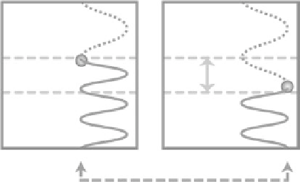
(a) The drawing explains how the observed SHG phase depends on the position of the emitter along
the optical axis. The dotted line represents the laser light incident on the sample and the solid line represents SHG
light. The horizontal dashed lines indicate the axial position of the scatterer (upper line in the left panel, referring
to the reference arm; lower line in the right panel, referring to the object arm). The axial position of the emitter is
determined directly from the phase of the generated second-harmonic field. (b) The drawing explains the relation
between the axial position of the SHG emitter (in the object space) and that of its image plane (in the image space).
The axial position of the emitter is determined from the hologram reconstruction distance
d
that brings the image
into focus. (From Shaffer, E., Marquet, P. and Depeursinge, C. 2010. Real time, nanometric 3D-tracking of nanopar-
ticles made possible by second harmonic generation digital holographic microscopy.
Opt. Express,
18: 17392-17403.
With permission of Optical Society of America.)