Biomedical Engineering Reference
In-Depth Information
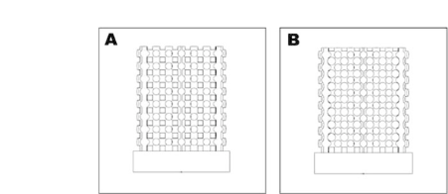
Figure 45.5.
Frontviewofscaffoldmodels:(a)scaffoldwithasquarepore
shape and (b)scaffold with a round pore shape.
scaffold models with a customized shape, complex architecture,
and required pore size and porosity can be achieved. Figure 45.5
showstwoscaffoldmodelswithdifferentporestructures,whichare
designedbyusingSolidworks
R
.Differentporestructures(withcon-
cave or convex pore surfaces) could have different effects on the
cellular behavior.
45.4 Fabrication of Nanocomposite Scaffolds via SLS and
Characteristics of the Scaffolds
Two porous scaffold models, namely, a bar-shaped scaffold model
and a rod-shaped scaffold model, as shown in Fig. 45.6A,C, with 3D
periodicarchitecturesweredesignedusingSolidWorks
R
inthecur-
rent investigation.
To improve the quality of sintered scaffolds and facilitate scaf-
fold handling, a solid base was incorporated in the scaffold design.
The scaffold models consisted of a repeating array of struts. The
bar-shaped model had a strut size of 0.5 mm and a pore size of
1.0 mm, and the rod-shaped model had a strut diameter of 1.0
mm and a pore size of 0.8 mm. Using the PHBV microspheres and
Ca-P/PHBV nanocomposite microspheres, PHBV scaffolds and Ca-
P/PHBV nanocomposite scaffolds, as shown in Fig. 45.6B,D, were
successfully fabricated via SLS. The sintered scaffolds had good


Search WWH ::

Custom Search