Biomedical Engineering Reference
In-Depth Information
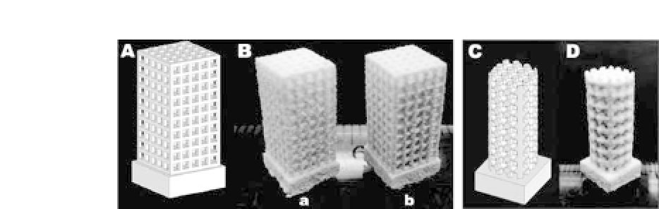
Figure 45.6.
Bar-shaped and rod-shaped scaffold models and sintered
scaffolds: (A) bar-shaped and (C) rod-shaped model in trimetric view;
(B)sinteredscaffolds,(a)PHBVscaffoldand(b)Ca-P/PHBVnanocomposite
scaffold, (D)sintered Ca-P/PHBV nanocomposite scaffold.
structure and handling stability, and hence loose microspheres
entrapped in the sintered scaffolds could be easily removed. The
macrostructure, including the height, width, and thickness, of sin-
teredscaffoldscouldbewellcontrolledbyselectingcarefullytheval-
ues of various SLS parameters. However, it was not easy to achieve
high accuracy for the pore size and strut size of scaffolds because
of the growth effect in the SLS process as well as the limitation of
resolution ofthe SLS machineused.
59
The typical layer morphology of bar-shaped PHBV scaffolds and
Ca-P/PHBV nanocomposite scaffolds is shown in Fig. 45.7. The SEM
imagesindicatedthatthemorphologyandarchitectureofeachlayer
of the scaffold were well preserved for both types of materials and
the pores were clearly identified and comparable to the designed
scaffold structure. The entrapped microspheres had been easily
removedfromthescaffoldsbymanualshaking.Withthecloseexam-
ination of the strut surface, as shown in Fig. 45.7b,d, it could be
seen that there was necking between adjacent microspheres and
nearly intact microspheres without obvious fusion also existed. The
presence of nearly intact microspheres could be explained as the
sticking of microspheres onto the sintered strut due to very small
melting of these microspheres caused by the heat generated during
the SLS process. The porosity of the designed scaffold model was
calculated to be 67.9% for the bar-shaped scaffold and 53.5% for
the rod-shaped scaffold using the SolidWorks
R
software. For sin-
tered scaffolds, the measured porosity values were 80.7
±
0.7% for


Search WWH ::

Custom Search