Biomedical Engineering Reference
In-Depth Information
B
A
C
D
1.10
0
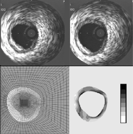
Figure 12.10:
(A) Template image of a coronary artery that does not have a fully
developed lipid core. (B) Corresponding target image of the artery under 16 kPa
internal pressure load. (C) FE mesh of the image space. (D) Circumferential
stretch distribution within the arterial wall and lesion.
The boundaries of the media/lesion were manually segmented in the lVUS
template image of the diseased vessels. B-spline curves were fitted to the points
generated by segmentation. These curves defined the boundaries of the arterial
wall. A 2D plane strain FE model was constructed for each vessel that included
the entire image domain Figs. 12.9 C and 12.10C). The lumen and the tissue sur-
rounding the vessels were represented by an isotropic hypoelastic constitutive
model with relatively soft elastic material properties (E
=
1.0 kPa and
ν
=
0
.
3) to
provide tethering. The outer edges of the image domain were fully constrained
to eliminate rigid body motion. Transversely isotropic hyperelastic strain en-
ergy was utilized to describe nonlinear behavior of the arterial wall [57-64] and
atherosclerotic lesions [50, 54, 65, 66]. This strain energy definition describes a
material that consists of fibers imbedded in an isotropic ground substance. The
strain energy function was defined as:
K
2
W
=
F
1
(
I
1
,
I
2
)
+
F
2
(
˜
[ln (
J
)]
2
λ
)
+
(12.33)
F
1
represents the behavior of the ground substance while
F
2
represents the
behavior of the collagen fibers. The final term in the expression represents the