Biomedical Engineering Reference
In-Depth Information
were mounted in a position approximating the artery orientation
in situ
. The
left main coronary artery was cannulated, and the side branches were ligated
to reduce flow until a constant physiological perfusion pressure could be main-
tained. IVUS images were acquired using a clinical IVUS system, comprising an
HP Sonos 100 ultrasound console and a 30 MHz, 3.5 F Boston, scientific monorail
intracoronary ultrasound imaging catheter using parameters typical for clinical
study. The IVUS catheter was inserted into the vessel as halfway down the
LAD. The arterial internal pressure monitored using a Millar 4 F pressure trans-
ducer introduced through a distal cannula placed approximately adjacent to
the IVUS catheter. The vessel was then perfused with 37
◦
C physiological saline
until a 16.00 kPa (120 mmHg) internal pressure load was achieved. The IVUS
images acquired under 0 kPa were designated the
template
images (Figs. 12.9A
and 12.10A), while the images acquired with the artery under 16.00 kPa (120
mmHg) internal pressure load were designated the
target
images (Figs. 12.9B
and 12.10B).
A
B
D
C
1.10
0
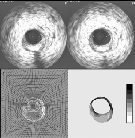
Figure 12.9: (A) template image of a coronary artery with a fully formed
lipid layer (arrow). (B) Corresponding target image of the artery under
16.00 kPa internal pressure load. (C) FE mesh representation of the image
space. (D) circumferential stretch distribution within the arterial wall and
lesion.