Biomedical Engineering Reference
In-Depth Information
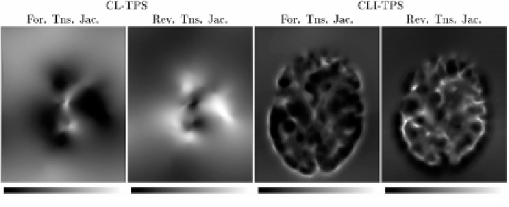
CL-TPS
CLI-TPS
For. Tns. Jac.
Rev. Tns. Jac.
For. Tns. Jac.
Rev. Tns. Jac.
Figure 6.9:
This figure shows the Jacobians of the forward and reverse trans-
formations for the registration of data sets
B
2 and
B
1 for the CL-TPS (left two
panels) and CLI-TPS (right two panels) algorithms. The bright pixels of the Jaco-
bian images represent regions of expansion, and dark pixels represent regions
of contraction.
algorithm. This is because the CL-TPS algorithm matches the images at the cor-
responding landmarks and smoothly interpolates the transformation between
the landmarks. Conversely, the patterning of the local distortions in the CLI-TPS
registration resemble the underlying intensity patterning. This indicates that
combining the intensity information with the landmark information provides
additional local deformation as compared to using the landmark information
alone. This improved registration between landmarks produces more distortion
of the template image and therefore there is a larger range of Jacobian values
for the CLI-TPS algorithm than the CL-TPS algorithm as shown by the color bar
scales.
Inverse consistency error images are computed by taking the Euclidean norm
of the difference between the forward and the inverse of the reverse transforma-
tions at each voxel location in the image domain. Figure 6.10 shows the inverse
consistency error images for the registration of data sets
B
2 and
B
5 using the
UL-TPS, CL-TPS, CI-TPS, and and CLI-TPS algorithms. Note that each image is
on its own color-scale and that the UL-TPS algorithm has 10 to 200 times more
maximum inverse consistency error than the consistent registration algorithms.
The UL-TPS algorithm had 50 to 500 times more average inverse consistency
error than the consistent registrations algorithms. This can be seen by compar-
ing large regions of bright pixels in the UL-TPS image to the small regions of