Biomedical Engineering Reference
In-Depth Information
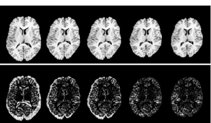
No Registration
UL-TPS
CL-TPS
CI-TPS
CLI-TPS
Figure 6.8:
Intensity matching results for registering dataset
B
5 to dataset
B
2
with the four registration algorithms. The top row shows the data set
B
5 trans-
formed into the shape of
B
2 using each algorithm and the bottom row shows the
absolute difference image between the transformed
B
5 image and the target
B
2
image. Note that the intensity difference images of the CI-TPS and CLI-TPS are
very similar since both algorithms minimize the intensity differences between
the deformed template and target images. However, the difference between
these two results is that the CLI-TPS also produces much smaller landmark
errors which cannot be seen in the intensity difference images.
smaller landmark errors than the CI-TPS method which cannot be seen in the
intensity difference images.
The images in Fig. 6.9 show the Jacobian of the forward and reverse transfor-
mations between images
B
2 and
B
1 produced by the CL-TPS (left two panels)
and CLI-TPS (right two panels) algorithms, respectively. The value of the Jaco-
bian at a point is encoded such that bright pixels represent expansion, and dark
pixels represent contractions. Notice that the intensity pattern of the forward
and reverse Jacobian images appear nearly opposite of one another since ex-
pansion in one domain corresponds to contraction in the other domain. These
images show the advantage of using both landmark and intensity information
together as opposed to just using landmark information alone. Notice that the
CL-TPS algorithm has very smooth Jacobian images compared to the CLI-TPS