Biomedical Engineering Reference
In-Depth Information
the UL-TPS and the CL-TPS algorithm. The arrows in the first and second panels
show the displacement between the corresponding landmarks in the forward
and reverse directions, respectively. The four landmarks in the corners of the im-
ages were fixed. The forward transformation
h
maps the four inner points to the
four outer points and the reverse transformation
g
maps the outer points to the
inner points. Applying the CL-TPS transformations to a rectangular grid shows
that the forward transformation—defined with respect to a Eulerian frame of
reference—causes the center of the image to expand (third panel of Fig. 6.4)
while the reverse transformation causes a contraction of the central portion of
the image (fourth panel of Fig. 6.4).
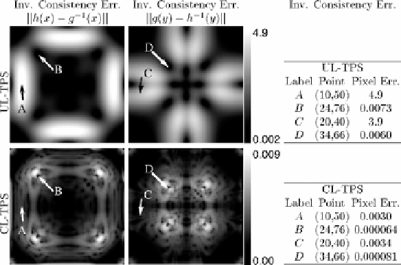
The top row of Fig. 6.5 shows the spatial locations and magnitudes of the
inverse consistency errors of the forward and reverse transformations generated
by the UL-TPS algorithm. The images in the left column were computed by taking
the Euclidean norm of the difference between the forward transformation
h
and the inverse of the reverse transformation
g
−
1
. The images in the center
column were computed in a similar fashion with
g
and
h
−
1
. The CL-TPS result
Figure 6.5:
The left and center panels show the inverse consistency errors of
the forward and reverse transformations, respectively. The tables in the right
columns list the landmark errors associated with selected image points. The top
and bottom rows are the inverse consistency errors associated with the unidirec-
tional (UL-TPS) and consistent (CL-TPS) landmark thin-plate spline algorithms,
respectively.