Biomedical Engineering Reference
In-Depth Information
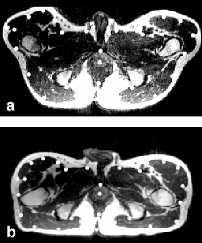
Figure 3.9: Control point selection when images are acquired in the treatment
and diagnostic positions. Image (a) is from the reference volume acquired in
the treatment position with legs raised. Image (b) is to be warped and is from
the volume acquired in the diagnostic position with the subject supine on the
table. Transverse slices best show the deformations, especially at the legs. As
described in the text, control points indicated by the white dots are selected
around the pelvic surface and the prostate. Each control point is located at
one voxel but displayed much bigger for better visualization. Volumes are from
volunteer S2.
because they provided other structures that can be missed in the transverse
images. It was also important to include CPs from organs other than the
prostate because they constrained warps. We always placed CPs at critical re-
gions such as the prostate center, pelvic surface, bladder border, and rectal
walls.
For registration of image volumes with full and empty bladder, most CPs
were placed from sagittal slices because they best showed the deformation of
the bladder and rectum (Fig. 3.10). About 10-20 CPs were placed at the borders
of the bladder and rectum on each of 8-10 sagittal slices with an equal interval
of
≈
8 mm, covering the entire pelvic region including the prostate, bladder, and
rectum.