Geology Reference
In-Depth Information
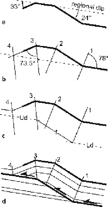
Fig. 11.39.
Construction of a complete
fault-bend fold starting with a
single horizon.
a
Starting fold
geometry with dips measured
from regional dip.
b
Axial sur-
faces bisect hinges.
c
Location
of the fault.
Ud:
upper detach-
ment;
f:
fault ramp;
Ld:
lower
detachment.
d
Final geometry
in the footwall may serve to locate the detachments. Alternatively, the stratigraphic
section may contain known detachment horizons that can be utilized in the interpre-
tation. Additional controls from the model are that axial surfaces 1 and 2 always termi-
nate at the upper detachment, and axial surface 1 always terminates at the base of the
ramp. Axial surface 3 can be on the ramp or at the top of the ramp. Having determined
the best location for the fault, the dip domains can be filled in with the appropriate
stratigraphy (Fig. 11.39d) and the interpretation is complete.
Since the pioneering work by Suppe (1983), there have been numerous papers de-
scribing models for flexural-slip fault-related folds. The following is a representative
list of significant papers on the topic: Jamison 1987; Chester and Chester 1990; Mitra
1990; Suppe and Medwedeff 1990; Jordan and Noack 1992; Suppe et al. 1992; Mitra
1993; Epard and Groshong 1995; Homza and Wallace 1995; Wickham 1995; Poblet and
McClay 1996; Poblet et al. 1997; Medwedeff and Suppe 1997; Suppe et al. 2004. The
recent topic by Shaw et al. (2005) is an excellent discussion of the application of mod-
els to compressional structures. Predictions based on 3-D axial-surface geometry are
described by Shaw et al. 2005b and Rowan and Linares 2005).