Geology Reference
In-Depth Information
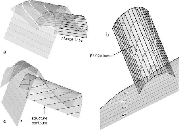
Fig. 6.40.
3-D views of the map in Fig. 6.39.
a
Oblique view to NW. Topographic surface with
white
contours
, fault w ith
thin black contours
, fold w ith
thick black plunge lines
.
b
Vertical view, N up. Struc-
ture contours (with elevations) and plunge lines on the fold, structure contours (with elevations) only
on the fault.
White line
is outcrop trace of fold.
c
Oblique view to NW. Same as
a
except fold shape
indicated by structure contours
is projected south, up plunge, along the plunge lines onto the structure contour map
of a fault. The intersection points where the plunge lines have the same elevation as
the fault contours are marked and then connected by a line that represents the trace
of the marker horizon of the fault plane (Fig. 6.39). In 3-D (Fig. 6.40a), the outcrop
trace is projected up and down plunge from the outcrop trace to more completely
illustrate the fold.
A structure contour map can be constructed from the plunge lines by joining the
points of equal elevation (Fig. 6.40b). Figure 6.40b demonstrates that the plunge lines
are not parallel to the structure contours and that projections should be made parallel
to the plunge lines, not parallel to the structure contours. The structure contours pro-
vide an additional cross check on the geometry of the structure and on the internal
consistency of the data. Once the fold geometry is constructed the plunge lines can be
deleted and the shape shown by structure contours alone (Fig. 6.40c).
This technique can be performed analytically using the method of De Paor (1988).
An individual point P (Fig. 6.41), given by its
xyz
map coordinate position, can be pro-
jected along plunge to its new position P' (
x
', 0,
z
') on the cross-section plane (defined
by
y
' = 0). Select the map coordinate system such that
x
is parallel to the line of cross
section and
y
is perpendicular to the line of section. Choose
y
=
z
= 0 to lie in the plane