Graphics Programs Reference
In-Depth Information
Multiview Drawings
Multiview drawings may consist of elevation, plan, and sectional views. These views
are commonly used in 3D programs. Three-dimensional objects are often constructed
by creating the top (plan), front, and side (elevation) views of the object. Simple 3D
objects such as extrusions and lathed objects use cross-sections of the shape.
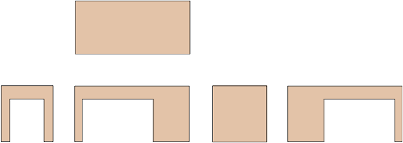
Multiview drawings are often called orthographic projections since they are typi-
cally rendered at right angles from one another. Figure 1.3 shows a typical multiview
arrangement of a simple 3D object. Although none of the multiview drawings separately
can truly represent the actual configuration of a three-dimensional object, there are
many times when just a front view or side view adequately conveys the sense of 3D
objects or space.
Top
Left Side
Front
Right Side
Back
Bottom
Figure 1.3
Typical multiview arrangement
Single-View Drawings
Single-view drawings present more than one side of an object in the same view. There
are two types of single-view drawings: paraline and perspective. In paraline drawings,
any two parallel lines or planes remain infinitely parallel, while in perspective draw-
ings, parallel lines appear to converge at one or more vanishing points. When drawing
or sketching by hand for generating 3D ideas or for scanning, paralines are faster and
easier to construct than perspectives.


Search WWH ::

Custom Search