Graphics Programs Reference
In-Depth Information
Paraline Drawings
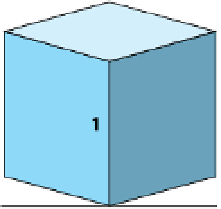
Figure 1.4 shows an example of two of the most frequently used paraline drawings,
both of which can easily be constructed. With isometric drawings, the three primary
axes of measurement include two ground-plane axes drawn at 30º angles from a
horizontal and a vertical height axis parallel to the picture plane. All measurements
are made along (or parallel to) these three axes at exact scale, which makes isometric
drawings the easiest to construct.
Exact shapes in each dimension are characteristic of isometric drawings. While they
are easy to construct, isometric drawings have a few drawbacks. A main one is that
the three visible faces are always turned at the same angle to the picture plane.
Another drawback is that isometric drawings tend to look somewhat unnatural due
to a lack of foreshortening.
Isometric
Symmetric Dimetric
Non-symmetric Dimetric
Figure 1.4
Isometric and dimetric drawings
Like isometric drawings, dimetric drawings have one axis parallel to the picture plane.
Dimetric drawings can be either symmetric or nonsymmetric as shown above. They are
characterized by having two of the three axes drawn at the same scale. Convenient
scale ratios such as 1:3/4 or 1:2/3 are normally used. Dimetric drawings tend to look a
little more realistic than isometric drawings because of foreshortening. In addition, the
nonsymmetric versions provide the advantage of enabling you to place more emphasis
on important views while downplaying less exciting ones.
Another class of paraline drawings is oblique drawings as shown in Figure 1.5. True
size and shape are retained in plan oblique drawings. The plan is usually tilted at an
angle, and the height lines are drawn as verticals. Different variations can be obtained
by changing the angle of the plan and altering the scale ratio between the plan and the
receding height lines.


Search WWH ::

Custom Search