Graphics Programs Reference
In-Depth Information
▶
11.
Click the upper-right circle marker on the lane subassembly you
inserted earlier.
A subassembly representing a curb and gutter is now attached to
the lane.
You may need to zoom
in to see the circle
markers on the lane
subassembly.
12.
Press Esc to end the assembly-insertion command. Click the lane
subassembly and the curb subassembly, and then click Mirror on
the ribbon.
▶
This isn't the same
Mirror command that
AutoCAD
®
software
uses for mirroring lines,
arcs, and circles. This is
a special command for
subassemblies, and it
must be used instead of
the AutoCAD version.
13.
Click the vertical red assembly baseline.
Both sides of the assembly now display a lane and curb subassembly.
14.
Save and close the drawing.
You can view the results of successfully completing this exercise by opening
Creating an Assembly - Complete.dwg
.
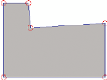
What Are Subassemblies Made of?
Subassemblies are made up of three fundamental components: points, links, and
shapes. A point is self-explanatory, a link is a line that is drawn between two
points, and a shape is the result of three or more links forming a closed shape, as
shown in the following diagram. Each point, link, and shape in a subassembly has
at least one code. These codes are used to identify the purpose of a component
and control its style, behavior, and relationship to other parts of the design.
A collection of styles that apply to multiple codes is called a
code set style
.
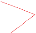
Links
Shape
Points
Creating a Corridor
Considering the complexity and sophistication of a corridor, the process
of creating one is actually quite simple. Once the alignment, profile, and
Certification
Objective