Graphics Programs Reference
In-Depth Information
assembly are in place, it's just a matter of telling these three objects that they
belong together. Of course, the design is far from complete at this point, but
as you'll see in the next exercise, creating the initial version of a corridor
involves only a few steps.
Exercise 9.2: Create a Corridor
◀
If you haven't already
done so, download
and install the files for
Chapter 9 according to
the instructions in the
Introduction.
In this exercise, you'll create the initial corridor for Jordan Court.
1.
Open the drawing named
Creating a Corridor.dwg
located in the
Chapter 09
class data folder.
2.
On the Home tab of the ribbon, click Corridor.
3.
In the Create Corridor dialog box, do the following:
a.
For Name, enter
Jordan Court
.
b.
For Alignment, verify that Jordan Court is selected.
Normally you would
also make a choice for
Target Surface, but for
now, leave this setting
set to <None>.
c.
For Profile, select Jordan Court FGCL.
d.
For Assembly, select Subdivision Road.
e.
Uncheck the box next to Set Baseline And Region Parameters.
◀
f.
Click OK.
4.
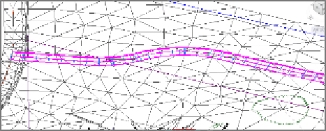
Zoom in to the bottom-right viewport, and notice the corridor that
has been created there (see Figure 9.7).
5.
Save and close the drawing.
You can view the results of successfully completing this exercise by opening
Creating a Corridor - Complete.dwg
.
FiGuRE 9.7
A portion of the newly created corridor shown
in a 3D perspective