Graphics Programs Reference
In-Depth Information
10.
Click one of the labels, and then click the square grip and drag it to
a new location that is clear of other lines and text. Repeat this for
the other labels to improve their appearance and readability.
The result should look similar to Figure 6.6.
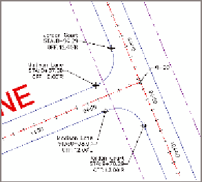
FiGuRE 6.6
Station/offset labels
applied to the edge-of-pavement arcs at the
intersection of Madison Lane and Jordan Court
11.
Save and close the drawing.
You can view the results of successfully completing this exercise by opening
Station Offset Labels - Complete.dwg
.
Creating Segment labels
So far, you have seen label groups that label the entire alignment at once and
station/offset labels that are typically used to label something other than the
alignment. What about the individual parts of the alignment? How do you
tell reviewers and contractors how to re-create those alignments in the field?
The answer is segment labels.
Segment labels
allow you to label things such
as bearings and distances for tangents and curve data for curves. By provid-
ing this information as text in the drawing, you give viewers of the drawing
the information they need to stake out the alignment in the field. You're also
sharing information about the geometric “performance” of the alignment
that might answer questions such as these: Are the curves too sharp for the
expected speed? Is the alignment parallel to other important features? Are
intersecting roads perpendicular to one another?
Segment labels stand alone like station/offset labels; however, you can create
them in bulk if you so desire. For example, all the tangents of an entire align-
ment can be labeled at once if you choose that option when creating the labels.