Graphics Programs Reference
In-Depth Information
Adding the Power Knob
A couple of quick constraints should lock everything in place:
1.
Place the power knob into the assembly.
2.
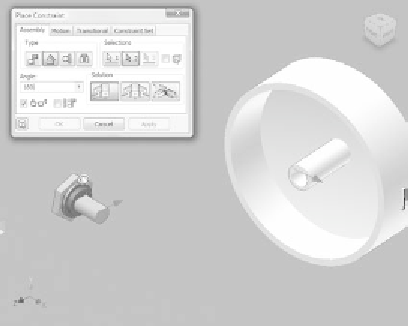
Place an Angular constraint between the edge of the fl at face on the
shaft of the switch and the edge of the fl at face in the hole on the
power knob, as shown in Figure 8.61. Set the Angle value to
180
degrees.
3.
Click OK to place the constraint.
4.
Place an Insert constraint (Figure 8.62) between the knob and the
switch. Click OK to complete the step.
5.
Save the assembly.
FIGURE 8.61
Mate the alignment flats just as they would be in a
physical model.
Now you have one major component left, and your design will be complete.
For the fi nal component, the grill, you'll use the starter part you downloaded.
With the name
grill
, you probably have a good idea what the part is. The Grill
tool that Inventor carries has a lot of tools within it for creating the mind-boggling
geometry that is referred to as a
grill
on modern plastic parts. These features can
be created using traditional modeling techniques, but doing so is a painful process
at best.


Search WWH ::

Custom Search