Graphics Programs Reference
In-Depth Information
2.
Start the Revolve tool. It should immediately pick up the outer sur-
face sketch.
3.
Click OK to create the outer surface.
4.
Press the Enter key to start the Revolve tool again. This time, it
detects the inner surface sketch.
5.
Click OK to create the inner surface.
6.
Save the fi le.
7.
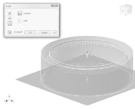
Click the Sculpt tool in the Surface panel of the Model tab.
8.
For Surfaces, pick the Origin XZ plane and then the inner and outer
surfaces.
The preview shows building a solid with no cavity.
9.
Pick the top arrow, as shown in Figure 8.55. This tells Sculpt that the
body is between the inner surface and the outer surface.
FIGURE 8.55
Telling Sculpt where the solid geometry should be formed
10.
Click OK to create the solid.
11.
Move the End of Part marker below Boss Sketch in the Browser.
12.
Extrude the profi le, as shown in Figure 8.56, using To Next Extents.
13.
Move the End of Part marker to the bottom of the list of features.
Now that you've used Sculpt and Extrude to form the model, you'll embellish
it with some text to indicate the state of power to the fan.


Search WWH ::

Custom Search