Graphics Programs Reference
In-Depth Information
Weldments
In Inventor, a
weldment
is a specialized assembly. To enable the weldment tools,
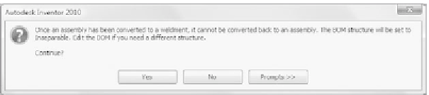
you'll need to convert a saved assembly to a weldment. Doing so will open the
Convert to Weldment dialog box (see Figure 4.19), where you'll set your welding
standard, the bead material, and the bill of material structure that will be used.
FIGURE 4.19
The Convert to Weldment dialog box
After you convert your assembly to a weldment, you can perform specialized
tasks on it, such as adding beveled edges to the parts to prepare them to be welded
together. What is important about this is the beveled edge (created with the
Chamfer tool) generated as a feature in the weldment assembly. The individual
part doesn't show this feature. This follows the traditional workfl ow used by
most manufacturers.
Preparation features (as well as Weld and Machining features added to
the assembly after it's welded) are placed in the Browser above the parts of the
assembly. This keeps things organized, because these features are all part of
the assembly.
A fi nal feature of a weldment is the ability to have Inventor generate weld
annotations in the 3D model, which you can reuse in the 2D drawing.
Let's convert your assembly to a weldment and fi nish it as a single component
rather than an assembly of two separate components:
1.
To make the conversion, go to the Convert panel of the Assembly tab,
and select the Convert to Weldment tool.


Search WWH ::

Custom Search