Graphics Programs Reference
In-Depth Information
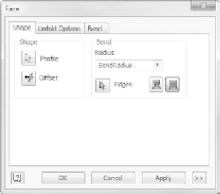
FIGURE 3.10
The Face dialog box
Often, you'd use a fl ange to create this type of geometry; but with your lofted
fl ange, it would be diffi cult to properly input the angle that lets this feature be
parallel with the XY plane. So, you'll create this as a Face feature and use the
Blend option:
1.
Start the Face tool. Because you only have one profi le in your sketch,
Inventor assumes you want to use your rectangle to create the face.
2.
Click the arrow button next to Edges.
3.
Select the outside edge of the lofted fl ange, as shown in Figure 3.11.
4.
Click OK to create the new Face feature.
Look closely at your component. Note that the bend relief next to
the new face/fl ange has a square bottom, and observe the thickness
of the part.
5.
Click the Sheet Metal Defaults tool.
6.
Select Aluminum - .13 from the Sheet Metal Rule pull-down, and
click OK to accept it as the rule that will now govern your part.
Note the change to the bend-relief shape and the slight change in
material thickness and color. It looks good; but for this part, you want
the bend that was added to the face to have a smaller bend radius.
7.
Double-click the icon next to Face1 in the Browser.
As with all Inventor tools, this will launch the same dialog you saw
when you created the feature.
8.
Change the Bend Radius value to
.05
.


Search WWH ::

Custom Search