Graphics Programs Reference
In-Depth Information
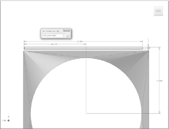
18.
Type
/2
after the dimension name, as shown in Figure 3.9.
19.
Click the green check mark to accept the new value. Change the
dimension name from the automatic name to
half_width
.
20.
Finish the sketch, and save your work.
Now, you'll use a new feature to convert this rectangle into a fl ange of sorts.
FIGURE 3.9
Using a formula in the dimension
The Face Tool
The Face tool is like an Extrude tool, but you don't have to set a distance. The
distance is determined by the thickness of the material. The only other rule is
that you have to have at least one closed loop in the sketch. Figure 3.10 shows
the dialog box; it's extremely useful if you need to add a fl ange to a part but the
fl ange will have an irregular shape. Very often, the Face tool is used to defi ne
the base feature of a sheet metal part.
In addition to having the usual option tabs and sketch-selection tools, the
Face tool can select edges to blend the face to. After an edge is selected, a pre-
view of how the bend will occur between the new face and the existing body
appears.


Search WWH ::

Custom Search