Graphics Programs Reference
In-Depth Information
3.
On the Quick Access Toolbar is a pull-down that allows you to change
the color of the part. Select the color of your choice. For the record, I
selected Blue Pastel for clarity in the images.
4.
Start the Flange tool, and zoom into the lower-left corner of the part.
5.
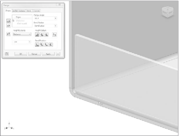
Select the inside edge of the bottom, as shown in Figure 2.30. A pre-
view of the fl ange as specifi ed appears.
6.
Select the inside edge of the left side, as shown in Figure 2.31.
When the second edge is selected, a corner treatment is applied
automatically. An icon appears at the corner along with one in the
center of each new fl ange. Selecting these icons brings up dialogs
that let you edit their placement properties on the fl y.
7.
Select the inside edges of the remaining two sides. The result should
preview as show in Figure 2.32.
FIGURE 2.30
Selecting an edge previews the flange feature.
8.
Click OK to place the four fl anges. They appear as a single feature in
the Browser: Flange1. The component should look like Figure 2.33.
9.
Save the fi le.
You could repeat the process for the opposite side; but instead, let's use
another tool.


Search WWH ::

Custom Search