Biomedical Engineering Reference
In-Depth Information
111 nm
Estimated tip shape
56 nm
0 nm
0
m
1.6
m
µ
µ
0
µ
m
1.6
µ
m
111 nm
56 nm
0 nm
0
µ
m
1.6
µ
m
0
µ
m
1.6
µ
m
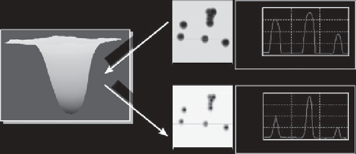
Fig. 2.32. Example of blind reconstruction and subsequent deconvolution of probe geometry. By
using the blind reconstruction technique, it is possible to calculate the probe geometry from the
image of the nanoparticles (top). Then the probe geometry can be removed from the entire image,
giving the sharper image shown below.
than electron microscopy, but both involve imaging an external sample, and could alter the
nature of the tip by contamination (e.g. by the nanospheres) or wearing (by the spike), and
the stability of a very sharp feature to repeated imaging by the AFM is uncertain [50].
However, using a technique called blind reconstruction, the geometry of a probe can be
calculated by carefully analysing an image of the sample of interest [50-53]. Blind
reconstruction works by assuming that the AFM image is formed by a dilation process
[54]. This means that not only does the tip probe the sample, but the sample also probes the
tip. In principle, each pixel in the image obtained contains information about the shape of
the AFM probe tip, as well as the information about the real sample topography. The idea
of blind reconstruction is to extract the information about the tip from each pixel. In order
to build up a picture of the tip from the information in the image, the correlation between
the neighbourhood of each pixel is compared to the neighbourhood of each other pixel in
the image. Essentially, the routine looks for any repeating patterns in the image, and
assumes that any such patterns derive from the shape of the tip. Such methods are very
computer intensive and it can take a long time to analyse a single image. For example, to
do the blind reconstruction on a single 512
512 pixel image with a Core2 processor can
take 5 minutes. Having obtained the geometry of the tip from the image, it is then possible
to mathematically remove the probe broadening artefacts from the image. As an example,
Figure 2.32 shows an AFM image of 100 nm diameter nanospheres, and the effects of
blind tip-shape reconstruction and subsequent image deconvolution on the image.
This technique has been shown to be highly effective under certain circumstances [45,
55], but it does have some limitations [54]. The tip profile extracted is not the real profile,
but an estimate of the profile of the bluntest tip that could have made the image. In
addition, imaging some samples will give a tip profile estimate that is closer to the real
shape than others. Specifically, samples with high roughness and steep features will lead to
a tip profile close to the real one. If the sample measured does not have these, it may be
necessary to image an external sample after imaging the sample of interest to get adequate