Hardware Reference
In-Depth Information
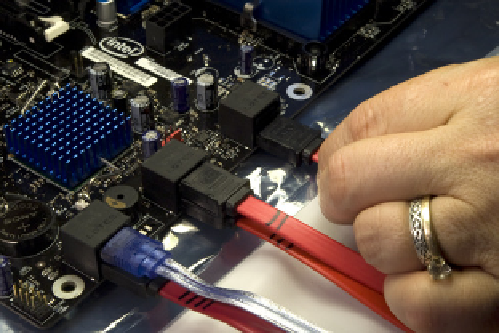
Figure 5-38.
Labeling a SATA data cable that will connect to SATA
port 2
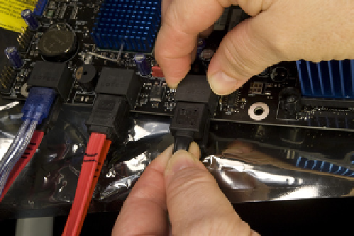
Figure 5-39.
Connecting the SATA data cables to the motherboard
The SATA data cable for the 2.5” removable drive bay is a
captive cable with a black sheath and connector. Locate it
among the bundle of front-panel cables at the top front
of the case, and connect it to SATA port 0, as shown in
Figure 5-40.
Seatingandsecuringthemotherboard
To begin, slide the motherboard into the case, as shown
in Figure 5-41. Carefully align the back-panel I/O connec-
tors with the corresponding holes in the I/O template,
and slide the motherboard toward the rear of the case
until the motherboard mounting holes line up with the
standoffs you installed earlier.
Figure 5-40.
Connect the captive black SATA data cable from the
top 2.5” removable drive bay
Chicken and Egg
It may be easier to connect the front-
panel switch/indicator and port cables
before you install the motherboard in
the case. The trade-off is that if you
install the motherboard first, you
have plenty of cable length, but the
pins you must connect those cables
to are deep in the case and hard to
get to. If you install the cables first,
the pins are more easily accessible,
but you have very little cable slack to
work with, both when you connect
the cables and when you slide the
motherboard into the case. We gen-
erally install the motherboard first
and worry later about getting all the
cables connected.
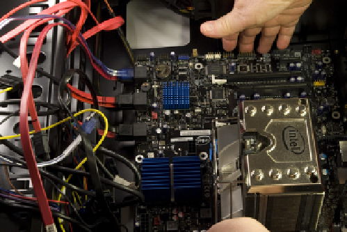
Figure 5-41.
Slide the motherboard into position, making sure the back-panel I/O connec-
tors align with the holes in the I/O shield
It's helpful to keep the front edge of the motherboard slightly raised as you
slide the motherboard into position. As the back-panel I/O connectors on the
motherboard come into contact with the back-panel I/O template, lower the