Hardware Reference
In-Depth Information
front edge of the motherboard until it is level and then press gently to seat the
back-panel ports in the template. In theory, at least, this prevents the metal
grounding tabs on the I/O template from intruding into the ports.
Before you secure the motherboard, verify that the back-panel I/O connectors
mate properly with the I/O template. Make sure none of the grounding tabs
intrude into a port connector. An errant tab at best blocks the port, rendering
it unusable, and at worst may short out the motherboard.
Less Is More (or Less)
When you install motherboard
mounting screws, you're also putting
torque on the standoffs. Tighten the
motherboard screws gently, using a
standard screwdriver. When you feel
tension, stop turning the driver. If you
overtorque the mounting screws,
you're also overtorquing the stand-
offs, which may strip. Particularly
if you're using an aluminum case,
don't even think about using a power
screwdriver.
After you position the motherboard and verify that the back-panel I/O con-
nectors mate cleanly with the I/O template, insert a screw through one mount-
ing hole into the corresponding standoff. You may need to apply pressure to
keep the motherboard positioned properly until you have inserted two or
three screws.
If you have trouble getting all the holes and standoffs aligned, insert two
screws but don't tighten them completely. Use one hand to press the mother-
board into alignment, with all holes matching the standoffs. Then insert one or
two more screws and tighten them completely. Finish mounting the mother-
board by inserting screws into all the standoffs and tightening them, as shown
in Figure 5-42.
After you install all of the mounting screws, do a final check to ensure that
none of the rear-panel I/O ports are fouled by grounding tabs on the I/O
shield, as shown in Figure 5-43.
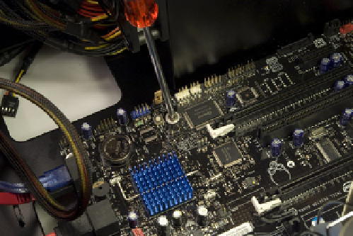
Figure 5-42.
Secure the motherboard by driving screws through
the mounting holes into the standoffs
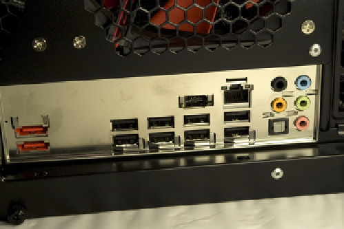
Figure 5-43.
Verify that none of the back-panel I/O ports are
fouled by the grounding tabs on the I/O shield
At this point, you can clear up the cable clutter a bit by routing the free ends
of SATA data cables 1 through 5 through the access cutout to the underside
of the motherboard tray. We'll fish them back through other cutouts when we
connect the drives.