Geology Reference
In-Depth Information
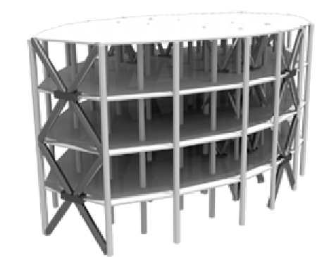
Figure 7. Four-story building model under earthquake excitation
of the four floors is supported by 43 columns of
circular cross section. All floors have a constant
height equal to 3.0 m, leading to a total height of
12.0 m. It is assumed that each floor may be
represented sufficiently accurately as rigid
within the
x
−
plane when compared with the
flexibility of the columns. Hence, each floor can
be represented by three degrees of freedom, i.e.
two translatory displacements in the direction of
the
x
axis and
y
axis, and a rotational displace-
ment. The associated active masses in the
x
and
y
direction are taken constant for all floors and
equal to 658 ton, while the mass moment of in-
ertia is equal to
1 8 10
5
acceleration is modeled as described in a previous
Section.
Dissipation Model
For an improved earthquake performance the
structural system is enforced with vibration con-
trol devices.
Ten devices connected to the structure every
two floors as indicated in Figure (7) are placed
in the structural system. A typical configuration
of the devices is shown in Figure (8). They con-
sist of brace and plate elements as indicated in
the figure. Between the plates there are a series
of dissipators in the form of metallic U-shaped
flexural plates (UFP).
The devices exhibit a one-dimensional hys-
teretic type of non-linearity modeled by the restor-
ing force law
.
×
ton-m
2
for all floors.
The Young's modulus
E
and the modal damping
ratios
ρ
i
of the structural model are treated as
uncertain system parameters. The Young's
modulus is modeled as a Gauss
i
an random vari-
able with most probable value
E
=
2 5 10
10
.
N/
m
2
,
and coefficient of variation of
20%,
while
the damping ratios are modeled by independent
Log-normal random variables with mean values
ρ
i
=
0 0.
and coefficients of variation of
40%
.
The structural model is excited horizontally by a
ground acceleration applied at
45
°
with respect
to the plan of the system. The induced ground
×
r t
=
n
r
t
(50)
( )
( )
ufp
ufp
where
n
ufp
is the number of U-shaped flexural
plates in the device and
r
ufp
( )
is the dissipator
t
force given by
Search WWH ::

Custom Search