Geology Reference
In-Depth Information
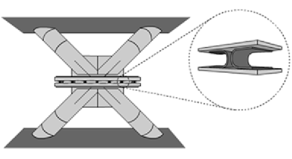
Figure 8. Vibration control device and metallic U-shape flexural plates
y
r
( )
t
=
α
k
δ
( )
t
+ −
(
1
α
)
k U z t
( )
(51)
k
e
=
4 10
8
N/m,
U
y
= ×
5 10
3
m,
α
=
0 01
−
.
,
ufp
e
e
= −
.
are used in this
case. These model parameters generate hyster-
etic behaviors similar to the one observed from
experimental data (De La Llera et al., 2004)
β
1
=
. ,
β
2
1 0
=
. ,
β
3
2 0
0 5
where
k
e
is the pre-yield stiffness,
U
y
is the yield
displacement,
α
is the factor which defines the
extent to which the restoring force is linear,
z
( )
is a dimensionless hysteretic variable, and
δ
( )
t
is the relative displacement between the floors
where the device is connected. The nonlinear
restoring force of the device acts between the
floors where it is placed with the same orientation
as the relative displacement
δ
( )
t
The hysteretic
behavior of each U-shaped flexural plate is defined
in terms of the auxiliary variable
z
( )
which sat-
isfies the first-order non-linear differential equa-
tion
Design Problem
The design variables denoted by
d i
=
1
are the diameters of the reinforced concrete column
elements. Each floor is associated to one design
variable and therefore
n
d
= 4
in this example.
The objective function
f
is proportional to the
total volume of the resistant elements (columns),
while the failure events are defined in terms of
the interstory drift ratios, and given by
,
, ...,
n
,
i
d
U z t
y
( )
( )
t
z t
( )(
sgn
( ( ))
t
sgn
( ( )))
z t
=
δ
β
−
β
δ
+
β
1
2
3
F d
({ },{ },{ })
max
θ
ξ
=
(52)
i
*
|
δ
( ,{ },{ },{ }) |
t
d
θ
ξ
>
δ
(53)
t k
,
=
1
,..,
2001
i
k
k
where
β
1
,
β
2
and
β
3
are dimensionless quanti-
ties that characterize the properties of the hys-
teretic behavior,
sgn(·)
is the sign function, and
all other terms have been previously defined.
The quantities
β
1
,
β
2
and
β
3
correspond to
scale, loop fatness and loop pinching parameters,
respectively. The above characterization of the
hysteretic behavior corresponds to the Bouc-Wen
type model (Baber and Wen, 1981). The values
where
δ
( ,{ },{ },{ })
is the relative displace-
ment between the
(
t
d
θ
ξ
i
k
−
1
-th floor evaluated at
the design
{ }
d
t
k
are the discrete time instants,
δ
*
is the critical threshold level and equal to
0 00
i i
, )
. 6
m (0.2
%
of the floor height),
{
θ
is the vector
that represents the uncertain structural parameters
(Young's modulus and damping ratios), and
{ }
ξ
Search WWH ::

Custom Search